Control method of hydraulic transmission system of power decoupling wave energy generation device

A technology of hydraulic transmission and power decoupling, which is used in the safety of fluid pressure actuation systems, ocean energy power generation, safety devices, etc., which can solve problems such as leakage, increase system unreliability, and affect the normal working state of hydraulic systems.

Inactive Publication Date: 2016-08-17
OCEANOGRAPHIC INSTR RES INST SHANDONG ACAD OF SCI
View PDF7 Cites 0 Cited by
  • Summary
  • Abstract
  • Description
  • Claims
  • Application Information

AI Technical Summary

Problems solved by technology

However, large-capacity accumulators have unfavorable factors such as high cost, heavy weight, and leakage after long-term use. The more important thing is that the power input of low pressure and large flow makes the response of the accumulator slow, and it is easy to mix gas, which seriously affects the hydraulic pressure. normal working state of the system
The above defects not only limit the adjustment and control of power by the hydraulic transmission system, but also increase the unreliability of the system.
[0004] Chinese patent CN 101737241A discloses a "wave power generation energy storage voltage stabilization constant frequency method and its device based on hydraulic transmission". The device mainly relies on a large-capacity accumulator to absorb energy fluctuations caused by wave changes. To achieve the adjustment of the generator speed; this method has a narrow range of speed regulation, which is not suitable for smooth speed control, and will still cause impact on the generator set

Method used


Image

  • Control method of hydraulic transmission system of power decoupling wave energy generation device
  • Control method of hydraulic transmission system of power decoupling wave energy generation device
  • Control method of hydraulic transmission system of power decoupling wave energy generation device

Examples


Embodiment Construction

[0026] The embodiments of the present invention will be further described below in conjunction with the accompanying drawings.

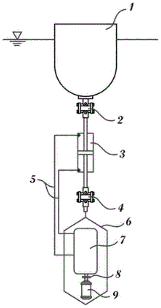
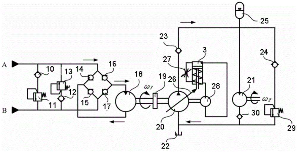
[0027] Such as figure 1 and figure 2 The shown buoy 1 reciprocates under the drive of the waves, driving the hydraulic cylinder 3 to produce reciprocating output and suction pressure oil. The one-way valve S1 10 and the overflow valve R1 11 play a role of safety limit on the upward chamber of the hydraulic cylinder 3. When When the pressure at the port A of the upward chamber is higher than the set pressure of the relief valve R1, the relief valve R1 is turned on, and the high-pressure oil flows back to the port A of the low-pressure chamber; The mouth pressure acts as a safety limiter. The pressure oil formed by the hydraulic cylinder 3 flows into the hydraulic motor M1 18 of the hydraulic transmission system 7 through the hydraulic rectification bridge located in the hydraulic pipeline 5; the hydraulic rectification bridge includes a one-way val...


PUM


Abstract

The invention discloses a hydraulic transmission system of a power decoupling type wave power generating device and a control method of the hydraulic transmission system of the power decoupling type wave power generating device. The transmission system is composed of an energy capturing unit, a pressure protection unit, a rectification unit, a voltage transformation unit, a speed regulating unit, an energy storage unit and a power generating unit. According to the hydraulic voltage transformation principle and the transmission system of the device, shaft connection is conducted on a hydraulic motor and a variable pump, low-voltage and large-flow input power is converted into high-voltage and small-flow output power, and therefore output power is more suitable for transmission and control; meanwhile, according to the control method, the voltage transformation ratio is adjusted in real time according to different operation sea conditions to stabilize the output rotation speed of the hydraulic motor and the output rotation speed of an electric generator, a high-voltage bag type accumulator is used for further stabilizing voltage fluctuation, conversion from a voltage transformation network to a quasi-constant-voltage network is achieved, and power coupling of input and output of the transmission system of the wave power generating device is achieved.

Description

technical field [0001] The invention belongs to the technical field of marine wave energy development and utilization, and in particular relates to a control method for a hydraulic transmission system of a power decoupling type wave energy generating device. Background technique [0002] Among many types of marine wave energy generating equipment, hydraulic wave energy generating devices are widely used, mainly because the hydraulic transmission system has large transmission power, small structure, fast response, can realize stepless speed change, and is easy to realize overload protection. and other advantages, and the pump-motor mode switching of the hydraulic system is easy, which is very suitable for low-speed and high-power equipment such as ocean wave power generation. At present, many wave power generation devices that have been maturely used in the world use hydraulic transmission. as a power transmission system. However, due to the characteristics of ocean wave ene...

Claims


Application Information

Patent Timeline
Patent Type & Authority Patents(China)
IPC IPC(8): F03B13/14F03B15/00F16H39/02F15B1/02F15B3/00F15B20/00
CPCY02E10/30
Inventor 崔晓程永强初士博惠力鲁成杰王志王成响
Owner OCEANOGRAPHIC INSTR RES INST SHANDONG ACAD OF SCI
Why Eureka
Try Eureka