Integrated scattering type oriented explosion cylinder
A decentralized and cylindrical technology, applied in blasting and other directions, can solve the problems of unsuitable four-way peripheral blasting, etc., achieve the effect of low cost, simple manufacturing process, and guaranteed transportation
- Summary
- Abstract
- Description
- Claims
- Application Information
AI Technical Summary
Problems solved by technology
Method used
Image
Examples
Embodiment 1
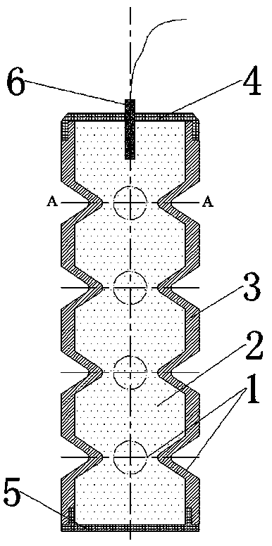
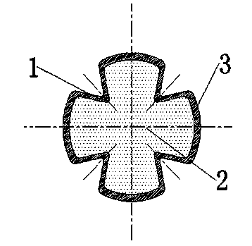
[0019] see figure 1 , to make a four-direction integrated decentralized directional explosion cylinder: the height of the cylinder 3 is 15cm, the outer diameter is 15mm, the wall thickness is 1.5mm, and the material is #45 steel. There are 16 conical pits 1 on the cylinder. The top angle is 80°, the length of the busbar in the pit is 4.5mm, and it is divided into four rows and arranged evenly, with 4 evenly distributed in each row, and the first row is evenly distributed at a distance of 30mm from the cylinder port. The distance between the centers of two adjacent rows of dimples in the longitudinal direction of the cylinder body 3 is 30 mm. One end of the cylinder is processed with external threads, and the other end is provided with internal threads of corresponding specifications. The position of the pit is marked on the cylinder according to the pre-design. A conical die with an angle of 80° is stamped to form the dimples. After all the pits are made, place them for natu...
Embodiment 2
[0024] Make two integrated decentralized directional explosive cylinders: the height of the cylinder is 8cm, the outer diameter is 12mm, the wall thickness is 2mm, and the material is #45 steel. One end of the cylinder is processed with external threads, and the other end is processed with internal threads of the same specification. There are 9 semicircular pits on the design cylinder, the diameter of the bottom of the pit is 6mm, and they are arranged in three rows, with 3 evenly distributed in each row, and the first row is evenly distributed 20mm away from the port of the cylinder. The distance between the centers of two adjacent rows of pits in the longitudinal direction of the cylinder is 20mm. Mark the position of the pit on the cylinder with upper and lower threads according to the pre-design, burn the steel pipe red with a liquefied gas-oxygen torch at the pit position, and then stamp it with a semicircular mold to form pits. After all the pits are made , placed to coo...
Embodiment 3
[0027]Make two integrated decentralized directional explosion cylinders: the height of the cylinder is 9cm, the outer diameter is 15mm, the wall thickness is 1.5mm, and the material is #45 steel. One end of the cylinder is processed with external threads, and the other end is processed with internal threads of the same specification. There are 8 conical pits on the design cylinder, the cone apex angle is 80°, the length of the busbar in the pit is 4.5mm, and it is divided into two rows, 4 evenly distributed, and the first row is evenly distributed from the cylinder Body port 30mm. The distance between the centers of two adjacent rows of pits in the longitudinal direction of the cylinder is 30mm. Mark the position of the pit on the cylinder with upper and lower threads according to the pre-design, burn the steel pipe red with a liquefied gas-oxygen torch at the position of the pit, and then stamp it with a conical die with an apex angle of 80° to form a pit. After the pits are...
PUM
| Property | Measurement | Unit |
|---|---|---|
| Outer diameter | aaaaa | aaaaa |
| Wall thickness | aaaaa | aaaaa |
Abstract
Description
Claims
Application Information
 - R&D
- Intellectual Property
- Life Sciences
- Materials
- Tech Scout
- Unparalleled Data Quality
- Higher Quality Content
- 60% Fewer Hallucinations
Browse by: Latest US Patents, China's latest patents, Technical Efficacy Thesaurus, Application Domain, Technology Topic, Popular Technical Reports.
© 2025 PatSnap. All rights reserved.Legal|Privacy policy|Modern Slavery Act Transparency Statement|Sitemap|About US| Contact US: help@patsnap.com


