Biomass thermal energy supply unit

A biomass and unit technology, applied in the field of stoves, can solve the problems of low heat energy utilization rate, large space occupation, high heat energy loss, etc., and achieve the effect of high heat energy utilization rate, compact main structure and small floor space

Inactive Publication Date: 2014-08-13
王宁
View PDF5 Cites 0 Cited by
  • Summary
  • Abstract
  • Description
  • Claims
  • Application Information

AI Technical Summary

Problems solved by technology

The deficiencies of this patented technology are: 1. The flue gas generator and heat exchange equipment are separately arranged, connected by pipes, complex in structure, large in size, large in space, high in heat energy loss, and high in manufacturing and production costs.
2. Coal is used as fuel, only one-stage heat exchange, the heat energy utilization rate is still low, and the temperature of the flue gas discharge port is still above 150 degrees
3. The dust-retaining and dust-exhausting device is set up in a simple and simple way, and the dust at the flue gas discharge port still exceeds the standard, failing to meet the requirements of environmental protection indicators

Method used


Image

  • Biomass thermal energy supply unit
  • Biomass thermal energy supply unit
  • Biomass thermal energy supply unit

Examples


Embodiment Construction

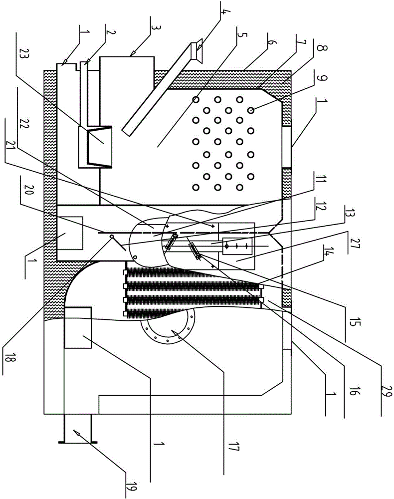
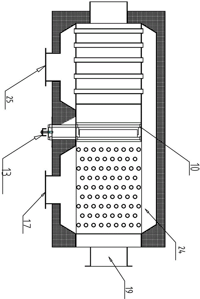
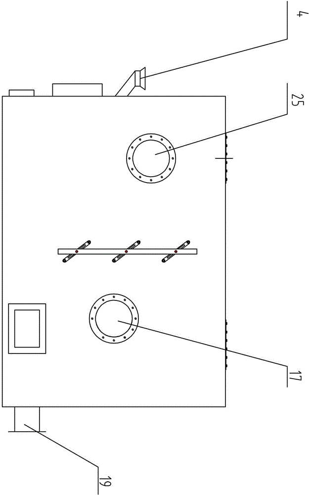
[0018] As shown in the figure; the biomass heat energy supply unit includes unit main body 6, fuel supply device, material combustion heating system, heat exchange system, dust-retaining and dust-discharging system 11 components; the front end of unit main body 6 is provided with a connection to the fuel supply device The fuel supply pipeline 4, the fuel supply pipeline 4 is connected with the burner 23, and the material combustion heating system is installed in the unit body 6, and the material combustion heating system is a secondary heat supply and heat exchange mode; above the front combustion chamber 5 in the unit main body The heat supply chamber and heat supply device are set in the middle and rear air inlet respectively to form a secondary heat supply system; the heat exchange system matched with the material combustion heat supply system is equipped with a secondary heat exchanger, and the primary heat supply system of the material combustion heat supply system The fir...


PUM


Abstract

The invention relates to a biomass thermal energy supply unit. According to the technical scheme, the unit mainly comprises a furnace, a material burning system, a dust discharge system and a heat exchange system and further comprises a unit body, a material supply unit, a material burning heat supply system, a heat exchange system and an ash blocking dust discharging system. The material burning heat supply system is arranged in the unit body, and a secondary heat supply and exchange mode (b) is used. A group of heat supply chambers is arranged above a burning chamber and in a rear air inlet of the unit body respectively to form a secondary heat supply system. A secondary heat exchanger is arranged on a heat exchange system matched with the material burning heat supply system, a primary heat supply chamber of the material burning heat supply system is matched with the secondary heat exchanger of the heat exchange system, and a secondary heat supply unit of the material burning heat supply system is matched with a primary heat exchanger of the heat exchange system. A smoke backflow retaining plate is arranged between heat supply channel ports corresponding to the upper portions of the two-stage heat exchangers, and an ash retaining dust discharging system is arranged at the position of the smoke backflow retaining plate.

Description

technical field [0001] The invention belongs to equipment for drying food materials, in particular to a stove. Background technique [0002] The existing hot blast stove body adopts a sandwich structure. After the fuel is burned in the combustion chamber, the flue gas is directly discharged through the exhaust pipe. The air enters through the combustion air inlet through the suction of the induced draft fan, and is directly discharged through the interlayer between the combustion chamber and the furnace body to the hot air outlet. Due to the insufficient heat exchange between flue gas and air in this structure, the exhaust gas temperature is too high, at least above 200°C, the thermal efficiency is low, and the air pollution is serious. [0003] In April 2013, the applicant applied for a utility model patent named "High-efficiency heat energy recovery unit for hot water boiler flue gas waste heat", (patent number: ZL201320200734.5), the hot flue gas produced by the utility ...

Claims


Application Information

Patent Timeline
IPC IPC(8): F26B23/02
Inventor 王宁
Owner 王宁
Why Eureka
Try Eureka