Cuttings Separation Method for Gas Drilling

A separation method and gas drilling technology, applied in construction and other directions, can solve the problems that the capacity of the cyclone separator cannot be too large, the gas processing capacity is small, and the solid phase content is high, and the effect of improving the primary separation effect is achieved.

Active Publication Date: 2016-05-04
BC P INC CHINA NAT PETROLEUM CORP +1
View PDF1 Cites 1 Cited by
  • Summary
  • Abstract
  • Description
  • Claims
  • Application Information

AI Technical Summary

Problems solved by technology

But this patent also has the following deficiencies: 1. Since the patent uses the principle of cyclone separation to remove particulate matter in the fluid, in order to ensure the separation effect, the capacity of the cyclone separator should not be too large, resulting in generally less gas processing capacity, so It cannot meet the current ubiquitous gas drilling cuttings separation operation under large volume conditions. Second, because the solid phase content in the fluid returned from gas drilling is extremely high, this patent uses a vacuum pump for liquid transportation and discharge, and the liquid contains a large amount of For solid phase particles, the stability of the vacuum pump to deal with liquids containing high solid phase particles is not high enough, so this patent cannot meet the continuous operation of gas drilling cuttings separation under long-term conditions
3. Due to the unknown formations drilled by gas drilling, situations other than those predicted by geological data may occur. At present, gas drilling often encounters unexpected formation water production. The formation water production has a strong randomness and cannot be accurately predicted. When the formation is drilled When the water comes out, the patent does not state whether it is possible to continue the gas drilling cuttings separation operation

Method used


Image

  • Cuttings Separation Method for Gas Drilling
  • Cuttings Separation Method for Gas Drilling
  • Cuttings Separation Method for Gas Drilling

Examples


Embodiment 1

[0047] A cuttings separation method for gas drilling, comprising the following process steps:

[0048] a. First start the circulating water treatment system, make the water in the whole system circulate and reach balance, and then start the gas drilling;

[0049] b. During drilling, the gas and solid returned from the wellhead are mixed with the circulating water of the circulating water treatment system to form a mixed fluid before separation, so that the dust in the solid is dissolved in the water;

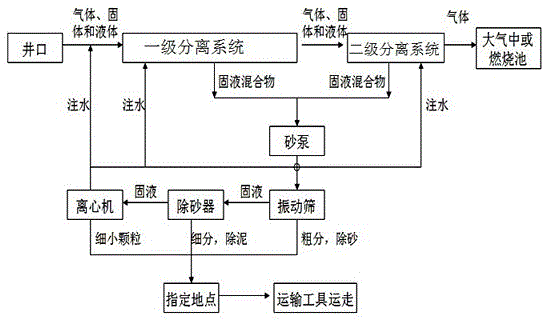
[0050] c. The mixed fluid first enters the primary separation system to remove coarse particles with a particle size greater than 10 microns, and the gas carries fine particles, water droplets or water mist to the secondary separation system, and after washing in a water bath, fine particles greater than 5 microns are removed , water droplets or water mist to obtain purified gas and solid-liquid mixture;

[0051] d. The solid-liquid mixture is sent to the circulating water trea...

Embodiment 2

[0066] The applicable drilling medium of the present invention is air, nitrogen and natural gas, and consists of a separation system and a circulating water treatment system, wherein the separation system is the core of the present invention. The separation system is divided into a first-level gravity, inertia and spray dust removal system and a second-level water bath washing system. The main function is to separate the gas in the return fluid from the solid-liquid, and the separated purified gas is directly discharged into the atmosphere or burned in the combustion pool. . The circulating water treatment system consists of a first-stage vibrating screen, a second-stage desander, and a third-stage centrifuge. The main function is to separate the solid from the liquid from the separation system. The solids are transported to the designated place. Specific steps are as follows:

[0067] 1. Before use, install the equipment on the sand discharge pipeline from the wellhead, and...

Embodiment 3

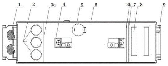
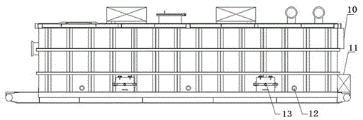
[0075] This embodiment illustrates the primary separation system in the present invention.

[0076] The first-stage separation system includes inlet diverter 1, anti-erosion baffle 2, first spoiler 3a, second spoiler 3b, first-stage stirring device 4, first-stage manhole 5, liquid level compensation port 6, nozzle Shower 7, primary exhaust port 8, overflow port 9, primary liquid level gauge 10, primary electric control box 11, primary sand discharge port 12, primary sand removal port 13, etc. The inlet splitter 1 divides the gas-solid-liquid mixed fluid into three paths and enters the first-stage separation tank. The whole separation device is skid-mounted, and the auxiliary pump is separated from the first-stage sand discharge port 12 and the liquid level compensation port 6 respectively. The liquid level in the tank is controlled to achieve the dynamic balance of the liquid level in the tank, and the first-level exhaust port 8 is directly connected to the ignition pool or th...


PUM


Abstract

The invention discloses a rock debris separating method for gas drilling. The rock debris separating method for gas drilling comprises the steps of firstly enabling water in a whole system to circularly flow to achieve balance and beginning to perform gas drilling; mixing gas and solid with the water to form a mixed fluid to enable dust in the solid to be dissolve in the water during drilling and before the gas returned from a well mouth and the solid are separated; enabling the mixed fluid to firstly flow into a primary separation system to remove coarse particles, discharging the gas carried with fine particles, water drops or water mist into a secondary separation system; removing the fine particles, water drops or water mist so as to obtain purified gas and a solid-liquid mixture after water bath washing is performed; delivering the solid-liquid mixture to a circulating water treatment system, and separating the coarse particles through primary treatment separation; removing the fine particles through secondary treatment separation; removing fine particles through tertiary treatment separation. The rock debris separating method for gas drilling can achieve returned fluid treatment under the condition that a grit chamber does not exist through gas drilling, gas meeting the direct emission standard is finally obtained, and the gas drilling requirement under different conditions can be met.

Description

technical field [0001] The invention relates to a cuttings separation method for gas drilling, which is used for separating the gas-solid-liquid mixed fluid returned from the wellhead during the gas drilling process, and replaces the existing gas drilling dust reduction method. Background technique [0002] In recent years, gas drilling technology has become increasingly mature, and its application scale has been continuously expanded, and it is actively developing into reservoir application. However, under the current technical conditions, the cuttings returned by gas drilling can only be separated by dust-fall water, and the outlet of the sand discharge pipeline must be connected to the sewage tank. If the gas is released from the formation, there is no ignition condition; , cuttings are easy to accumulate, affecting the subsequent use of the combustion pool. In addition, the dust reduction effect of the existing dust reduction method is not ideal, and the dust and water ...

Claims


Application Information

Patent Timeline
Patent Type & Authority Patents(China)
IPC IPC(8): E21B21/01
Inventor 罗整温杰许期聪邓虎李金和蒋杰肖劲超刘贵义
Owner BC P INC CHINA NAT PETROLEUM CORP
Why Eureka
Try Eureka