Device for automatically identifying and tracking multi-layer and multi-pass welding beads

A multi-layer multi-pass, automatic identification technology, applied in welding equipment, arc welding equipment, manufacturing tools, etc., can solve the problem of single-stripe difficult to identify multi-layer multi-pass welding, achieve simple structure, eliminate hysteresis, improve real-time effects

Inactive Publication Date: 2014-08-27
HARBIN INST OF TECH
View PDF9 Cites 25 Cited by
  • Summary
  • Abstract
  • Description
  • Claims
  • Application Information

AI Technical Summary

Problems solved by technology

[0005] The purpose of the present invention is to solve the problem that the single-stripe structured light of the existing welding method is difficult to identify the multi-layer multi-pass welding bead. The present invention provides a device for automatic identification and tracking of the multi-layer multi-pass welding bead

Method used


Image

  • Device for automatically identifying and tracking multi-layer and multi-pass welding beads

Examples


specific Embodiment approach 1

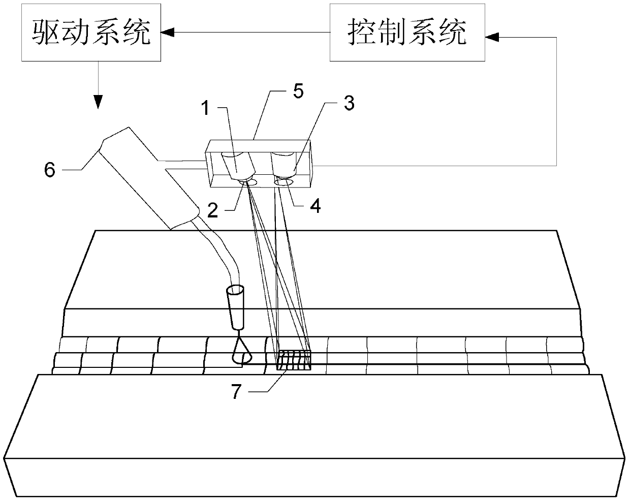
[0013] Specific implementation mode one: combine figure 1 Describe this embodiment, the device for automatic identification and tracking of multi-layer multi-run welds described in this embodiment, which includes a laser 1, a diffractive optical element 2, an image acquisition system, a control system, a drive system and a welding torch 6;

[0014] The cylindrical light emitted by the laser 1 is incident on the diffractive optical element 2, and the light passing through the diffractive optical element 2 forms a grid structured light, and the grid structured light is incident on the welding bead in front of the welding area. The image acquisition system is used to collect multiple The grid structured light and weld image on the multi-layer welding bead, the data collection output terminal of the image acquisition system is connected with the data collection input terminal of the control system, the welding torch 6 position and attitude control signal output terminal of the cont...

specific Embodiment approach 2

[0022] Embodiment 2: This embodiment is a further limitation of the device for automatic identification and tracking of multi-layer multi-run welds described in Embodiment 1. The image acquisition system includes a camera 3 and a narrow-band filter 4;

[0023] The narrow-band filter 4 is installed in front of the lens of the camera 3, and the output end of the acquisition signal of the camera 3 is connected with the input end of the acquisition signal of the control system.

[0024] The narrow band filter 4 is used to reduce arc interference.

specific Embodiment approach 3

[0025] Specific embodiment three: This embodiment is a further limitation of the device for automatic identification and tracking of multi-layer multi-run welds described in specific embodiment two, and the control system includes the following modules:

[0026] A module for receiving image data;

[0027] A module for performing data processing on the received image data;

[0028] A module for calculating the processed data to obtain welding seam trajectory information and welding torch 6 deviation information;

[0029] A module for outputting control signals for driving the position and posture of the welding torch 6 to the drive system according to the obtained welding seam track information and welding torch 6 deviation information.


PUM


Abstract

The invention discloses a device for automatically identifying and tracking multi-layer and multi-pass welding beads, which belongs to the technical field of welding, and aims at solving the problem that multi-layer and multi-pass welding beads are difficult to identify by the single-stripe structure light in the existing welding method. The device comprises a laser device, a diffraction optical component, an image acquisition system, a control system, a drive system and a welding gun, wherein the laser device emits a cylindrical light into the diffraction optical component; a grid structure light is formed by the light transmitting through the diffraction optical component; the grid structure light enters a welding bead in front of a welding area; the image acquisition system is used for acquiring the grid structure light and welding joint images on the multi-layer and multi-pass welding beads; the acquired data output end of the image acquisition system is connected with the acquired data input end of the control system; the welding gun position and attitude control signal output end of the control system is connected with the welding gun position and attitude control signal input end of the drive system; the welding gun position and attitude control signal output end of the drive system is connected with the welding gun position and attitude control signal input end. The device is used for automatically identifying and tracking the multi-layer and multi-pass welding beads.

Description

technical field [0001] The invention belongs to the technical field of welding. Background technique [0002] Automated welding is of great significance for improving welding conditions, increasing production efficiency, and ensuring welding quality. Automatic identification and tracking of weld seam is an important means to improve the level of welding automation. For example, during the welding process, the thermal deformation of the workpiece and the offset of the weld seam caused by the machining and assembly errors of the workpiece will lead to welding defects if the trajectory of the welding torch 6 is not adjusted. Especially for special environments such as underwater environment, nuclear radiation environment, and high-pressure toxic environment, it is difficult for operators to enter the welding work area to monitor the welding process at close range, and the welding seam must be automatically tracked and identified through appropriate sensing methods. [0003] I...

Claims


Application Information

Patent Timeline
Patent Type & Authority Applications(China)
IPC IPC(8): B23K9/127
CPCB23K9/1274
Inventor 李海超高洪明吕明达金泽石贾国庆张承浩
Owner HARBIN INST OF TECH
Why Eureka
Try Eureka