In-situ repair device and method for polluted water

An in-situ restoration and water body technology, applied in the field of water pollution treatment, can solve the problems of difficult to control its position, many manual operations, complex management, etc., and achieve the effect of easy-to-obtain materials, high degree of automation, and beautify the water environment

Inactive Publication Date: 2014-08-27
HENAN NORMAL UNIV
View PDF10 Cites 8 Cited by
  • Summary
  • Abstract
  • Description
  • Claims
  • Application Information

AI Technical Summary

Problems solved by technology

[0005] Chinese patent application number 200610076417.1, authorized announcement date is March 5, 2008, the name of the invention is ecological reactor for in-situ restoration of water body. The in-situ restoration of water body can not only improve the purification efficiency of water body restoration, avoid secondary pollution, but also reduce the cost. However, due to the constraints of natural weather factors, the purification effect of the ecological reactor for in-situ restoration of water body will be affected.
Chinese Patent Application No. 200310103050.4, published on October 27, 2004, the invention is called a horizontal swirl suspension carrier biofilm reactor and its in-situ repair method for water body. The invention starts from the characteristics of the in-situ repair reactor for water body. The structure of the reactor, carrier selection and dosage are optimized, so that when the reactor is in normal operation, the carrier particles can be fully suspended under the condition of higher carrier dosage and lower aeration, and Maintain the state of horizontal swirling flow, thereby effectively improving the removal rate of organic pollutants and ammonia nitrogen in the reactor, but this device is greatly affected by water flow, it is difficult to control its position in rivers and lakes, and there are many manual operations and complicated management

Method used


Image

  • In-situ repair device and method for polluted water

Examples


Embodiment Construction

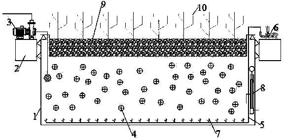
[0012] Embodiments are described in detail with reference to the accompanying drawings. An in-situ remediation device for polluted water, including a microbial treatment system and a phytoremediation system arranged above the microbial treatment system, wherein the microbial treatment system mainly consists of a microbial reaction tank 1, a floating tank 2, a drainage pump 3, a suspended filler 4, and an air duct 5. Composed of fan 6, aeration head 7 and automatic water inlet valve 8, the floating box 2 is fixed around the top of the microbial reaction box 1 through a tripod, and the floating box 2 makes the whole device under the action of gravity and buoyancy To achieve balance, in order to maintain the stability in the water, the floating box 2 adopts a clinker floating box with a size of 0.5m*0.5m*5m, the microbial reaction box 1 adopts a cast iron box with a size of 5m*5m*2m, and the drainage pump 3 is fixed on Above the floating tank 2, the water inlet of the drainage pu...


PUM


Abstract

The invention discloses an in-situ repair device and method for polluted water. The in-situ repair device is characterized by comprising a microbial treatment system and a plant repair system arranged above the microbial treatment system, wherein the microbial treatment system mainly consists of a microbial reaction tank, a floating box, a drainage pump, suspended filler, an air hose, a fan, an aerating head and an automatic water inlet valve. The plant repair system comprises a plant fixing layer and a functional plant fixed on the plant fixing layer. The invention further discloses a method for purifying a water body by using the in-situ repair device for polluted water. According to the invneiton, the purpose of in-situ repair of the polluted water by means of microorganisms which degrade pollutants in water and plants which absorb element such as nitrogen and phosphorus in water is realized.

Description

technical field [0001] The invention belongs to the technical field of water pollution treatment in environmental protection, and in particular relates to an in-situ restoration device for polluted water and a method thereof. Background technique [0002] With the progress of society and the development of science and technology, the number of various industrial factories is increasing day by day. While promoting economic development, these factories have also brought threats to the living environment. Environmental problems have developed from local to global threats. Water is the source of life, and a large number of pollutants enter the water body, resulting in eutrophication of the water body, a serious drop in water environment indicators, and an extremely serious threat to the survival of organisms, such as the Huaihe River Basin in my country. All countries in the world are paying more and more attention to sewage treatment and reuse technology, realizing the sustain...

Claims


Application Information

Patent Timeline
IPC IPC(8): C02F3/34C02F3/32
CPCY02W10/10Y02W10/33Y02W10/37
Inventor 申战辉沈帅兵王春峰
Owner HENAN NORMAL UNIV
Why Eureka
Try Eureka