Coupling and packing system and method for full-automatic PLC subdivider
A packaging system and splitter technology, applied in the field of electronic information, can solve problems such as large loss value, and achieve the effects of reducing packaging time, fast data transmission, and fast packaging
- Summary
- Abstract
- Description
- Claims
- Application Information
AI Technical Summary
Problems solved by technology
Method used
Image
Examples
Embodiment 1
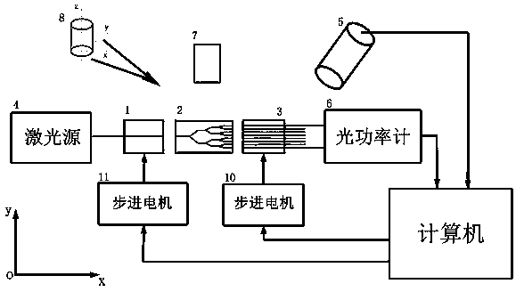
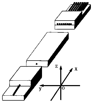
[0031] see figure 1, this automatic PLC splitter coupling packaging system mainly includes input optical fiber array (1), PLC optical splitter chip (2), output optical fiber array (3), laser light source (4), scattered light microscopic detector (5), dual-channel optical power meter (6), two microscopic monitoring cameras (7, 8), computer (9), two stepper motors (10, 11), UV lamp motor and optical platform, its characteristics It is: the two microscopic monitoring cameras (7, 8) are placed above and behind the PLC optical splitter chip (2) respectively, and are used to monitor the input and output optical fiber arrays (1, 3) and the PLC optical splitter The alignment between the chips (2); the laser light source (4) is connected to the optical fiber at the input end of the input fiber array (1); the dual-channel optical power meter (6) is respectively connected to the output of the output fiber array (3) The optical fibers of the first and eighth channels at the end; the scat...
Embodiment 2
[0033] This embodiment is basically the same as Embodiment 1, and the special points are as follows: 1. The wavelength of the light emitted by the laser light source (4) is 1310nm; 2. The stepping motors (10, 11) are controlled by the computer (9 ) control, which can move back and forth, left and right, up and down, thereby driving the input and output optical fiber arrays (1, 3) placed above it to move back and forth, left and right, up and down; To collect the pictures of the input fiber array (1), the PLC optical splitter chip (2) and the output fiber array (3) respectively on the XoZ and XoY planes, and enlarge them by 20 times; 4. The microscopic detection of scattered light Align the device (5) above the PLC optical splitter chip (2) at an angle of 45 degrees, and the lower the intensity value of the detected scattered light, it indicates that the input and output optical fiber array (1) is aligned with the PLC optical splitter (2). more accurate.
Embodiment 3
[0035] see Figure 1~Figure 5 , the automatic PLC optical splitter coupling packaging system and method, the above-mentioned system is used for packaging, and the packaging process steps are as follows:
[0036] A. Cleaning: Clean the surface of input fiber array (1), PLC optical splitter chip (2) and output fiber array (3);
[0037] B. Fixing: Fix the input fiber array (1), PLC optical splitter chip (2) and output fiber array (3) on the six-dimensional precision adjustment frame, and watch the two microscopic surveillance cameras (7, 8) Output the image to the computer (9), and manually adjust the position of the input and output optical fiber arrays (1, 3);
[0038] C. Coarse scanning at the input end: Turn on the 1310nm laser light source (4), and the light intensity value corresponding to each step of the input fiber array (1) is detected by the scattered light microscopic detector (5) above the chip, and the input fiber array ( 1) Move to the position corresponding to t...
PUM
 Abstract
Description
Claims
Application Information
 - R&D
- Intellectual Property
- Life Sciences
- Materials
- Tech Scout
- Unparalleled Data Quality
- Higher Quality Content
- 60% Fewer Hallucinations
Browse by: Latest US Patents, China's latest patents, Technical Efficacy Thesaurus, Application Domain, Technology Topic, Popular Technical Reports.
© 2025 PatSnap. All rights reserved.Legal|Privacy policy|Modern Slavery Act Transparency Statement|Sitemap|About US| Contact US: help@patsnap.com


