Rotary kiln with power generation device

A technology of power generation device and rotary kiln, which is applied in the field of rotary kiln and rotary kiln with power generation device, can solve the problems of incapable of making full use of waste heat energy resources of flue gas, and achieve the advantages of reducing energy consumption, improving quality and increasing economic benefits. Effect

Active Publication Date: 2014-09-03
SHIJIAZHUANG XINHUA IND FURNACE CO LTD
View PDF5 Cites 22 Cited by
  • Summary
  • Abstract
  • Description
  • Claims
  • Application Information

AI Technical Summary

Problems solved by technology

However, the internal combustion rotary lime kiln is not the above-mentioned large-scale rotary kiln, and can

Method used


Image

  • Rotary kiln with power generation device
  • Rotary kiln with power generation device
  • Rotary kiln with power generation device

Examples


Embodiment 1

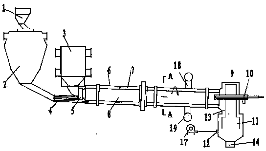
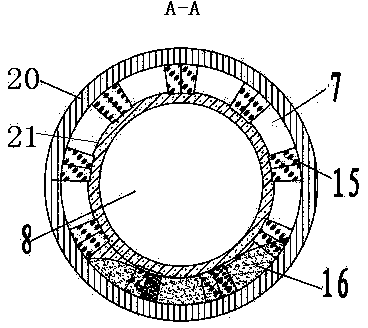
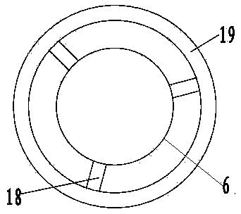
[0017] The rotary kiln with power generation device of the present invention is such as figure 1 As shown, it includes power generation device 3, feeding equipment 1, silo 2, kiln head 9, kiln body 6, kiln tail cover 5, gas collecting pipe 19, cooler 11, discharge port 14, screw conveyor 4 and cooling fan 17. Such as figure 2 As shown, the kiln body is composed of an inner cylinder 21 and an outer cylinder 20. The middle of the inner cylinder is a kiln 8 and the kiln is lined with refractory materials. The annular space 7 formed between the inner tube and the outer tube is the material chamber, and the annular space is provided with a support column 15 which fixes the inner tube and the outer tube and does not affect the passage of materials in the annular space. The kiln head on one side of the kiln chamber is provided with a burner 10, the burner is gas fuel, and the burner is connected with the air pipeline and the fuel pipeline. The screw conveyor is located on one side o...

Embodiment 2

[0020] Another embodiment of the present invention is used for the dry distillation of pulverized coal to produce coal gas and coal tar. The device is equipped with low-temperature dry distillation equipment, and the dry distillation equipment has a partition wall type rotary kiln structure, which is the same as the rotary kiln structure in Example 1. One of the two rotary kilns is used for pulverized coal high temperature coking gas extraction, and the other is used for low temperature dry distillation oil extraction. The two sets of rotary kilns are respectively provided with a kiln head 9, a kiln body 6, a kiln tail cover 5, a gas collecting pipe 19, a kiln chamber 8, an annular space 7 and a screw conveyor 4. The high-temperature dry distillation rotary kiln is equipped with a power generation device, a burnout chamber and a combustion-supporting fan. The power generation device is connected to the kiln bore of the high-temperature dry distillation rotary kiln. The burn-out...


PUM


Abstract

The invention relates to a rotary kiln with a power generation device. The rotary kiln comprises a power generation device, a material loading device, a material bin, a kiln body, a kiln end cover, a cooler and a cooling fan. A kiln head is provided with a burner; the kiln body is composed of an inner cylinder and an outer cylinder structure, a kiln chamber is in the middle of the inner cylinder, an annular space formed between the inner cylinder and the outer cylinder is a material chamber, and the annular space is provided with a support column; the rotary kiln is provided with a screw conveyor, a discharge passage and a gas collecting tube; the material loading device is connected with the material bin, the material bin is connected with the annular space through the screw conveyor, and the annular space through the discharge passage is connected with the cooler; and the lower part of the cooler is connected with a discharge hatch, the upper part of the cooler through the kiln head is connected with the kiln chamber, and the kiln chamber is connected with the power device. Through the kiln body with the inner cylinder and outer cylinder structure, limestone in the annular space is heated through flue gas dividing wall, so as to avoid direct contact of the flue gas with the material and benefit utilization and recovery of decomposed carbon dioxide gas; and at the same time, and waste heat of flue gas is utilized for power generation, so as to reduce the energy consumption of the rotary kiln.

Description

Technical field [0001] The invention belongs to the technical field of industrial furnaces, and relates to a rotary kiln, in particular to a rotary kiln with a power generation device. Background technique [0002] Rotary kiln refers to rotary calcining kiln, which belongs to building materials production equipment. Rotary kilns can be divided into cement kilns, metallurgical chemical kilns and lime kilns according to different materials. Cement kilns are mainly used for calcination of cement clinker, divided into two categories: dry production cement kilns and wet production cement kilns. Metallurgical chemical kilns are mainly used for the magnetic roasting of lean iron ore in steel plants in the metallurgical industry. Lime rotary kiln is a widely used kiln for calcination of small particles. It is suitable for steel, calcium carbide and non-ferrous metal production enterprises. It can directly calcine 10-40mm fine-grained limestone or dolomite. It has good raw material adap...

Claims


Application Information

Patent Timeline
IPC IPC(8): C04B2/10
CPCY02P40/40
Inventor 贾会平
Owner SHIJIAZHUANG XINHUA IND FURNACE CO LTD
Why Eureka
Try Eureka