Fork for clutch and manufacturing method thereof
A manufacturing method and clutch technology, applied in clutches, mechanical drive clutches, manufacturing tools, etc., can solve problems such as increased production costs and low material yields
- Summary
- Abstract
- Description
- Claims
- Application Information
AI Technical Summary
Problems solved by technology
Method used
Image
Examples
Embodiment 1
[0071] In weight ratio, mix C:3.8%, Si:1.5%, Mn:0.3%, P:0.01%, S:0.01%, Cu:0.2% and Fe as the rest, put all raw materials into medium frequency induction resistance furnace The temperature of the nodular cast iron stock solution (stock solution) taken out from the furnace is 1500°C.
[0072] Spheroidizing and inoculating the stock solution of nodular cast iron taken out from the furnace after smelting, adding rare earth ferrosilicon-magnesium alloy (FeSiMg6RE1) equivalent to 1.1% of the mass of the stock solution as a spheroidizing agent, as an inoculation The agent added barium ferrosilicon alloy (FeSi72Ba2) equivalent to 0.15% of the mass of the stock solution. As a result, it was confirmed that the components (wt%) of the melt were C:3.8, Si:2.3, Mn:0.3, P:0.01, S:0.01, Cu:0.2, and Mg:0.04.
[0073] The melt that has been spheroidized and inoculated is injected into the pre-prepared wet sand mold. The temperature of the melt is controlled at 1398°C, and it is cooled after ...
Embodiment 2
[0077] C: 3.6%, Si: 1.6%, Mn: 0.26%, P: 0.008%, S: 0.01%, Cu: 0.2%, and the rest of Fe are mixed and melted, taken out at 1510°C, and put into the stock solution to melt 1.1% FeSiMg6RE1 of liquid mass and 0.15% FeSi72Ba2 of raw liquid mass. The composition (wt %) of the melt subjected to the spheroidization treatment and the inoculation treatment was C: 3.6, Si: 2.3, Mn: 0.3, P: 0.008, S: 0.012, Cu: 0.3, and Mg: 0.045.
[0078] After that, the wet sand film is injected at a temperature of 1403°C for 8 minutes and then cooled. After machining the semi-finished product of the shift fork, it is subjected to austempering treatment. At this time, heat the semi-finished product of the shift fork to 910°C, keep it for two hours, and then put it into the nitrate solution at 350°C for 1.5 hours. Thereafter, after cooling to room temperature in the air, fine grinding and polishing are performed.
Embodiment 3
[0080] C: 3.4%, Si: 1.8%, Mn: 0.3%, P: 0.01%, S: 0.013%, Cu: 0.25% are mixed and melted as the rest of Fe, taken out at 1515°C, and put into the stock solution 1.1% FeSiMg6RE1 by mass and 0.15% FeSi72Ba2 by stock solution mass. The composition (wt%) of the molten solution subjected to spheroidization treatment and inoculation treatment was C:3.4Si:2.35, Mn:0.3, P:0.01, S:0.013, Cu:0.25, Mg:0.04.
[0081]Afterwards, inject the wet sand film at a temperature of 1410°C for 8 minutes and then cool it down. After machining the semi-finished product of the shift fork, it is subjected to austempering treatment. At this time, heat the semi-finished product of the shift fork to 920°C, keep it for two hours, and then put it into the nitrate solution at 360°C for 1.5 hours. Thereafter, after cooling to room temperature in the air, fine grinding and polishing are performed.
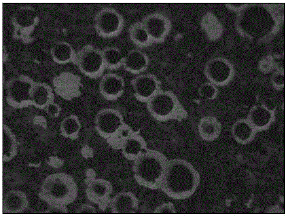
[0082] figure 1 For the photograph of the internal organization of above-mentioned embodiment 1, refer to fig...
PUM
 Abstract
Description
Claims
Application Information
 - R&D
- Intellectual Property
- Life Sciences
- Materials
- Tech Scout
- Unparalleled Data Quality
- Higher Quality Content
- 60% Fewer Hallucinations
Browse by: Latest US Patents, China's latest patents, Technical Efficacy Thesaurus, Application Domain, Technology Topic, Popular Technical Reports.
© 2025 PatSnap. All rights reserved.Legal|Privacy policy|Modern Slavery Act Transparency Statement|Sitemap|About US| Contact US: help@patsnap.com

