Drive unit of insulated gate power control device

A power control and driving device technology, applied in electrical components, pulse technology, electronic switches, etc., can solve the problem of not meeting the requirements of fast driving insulated gate voltage control devices, inability to quickly switch high-current devices, and low driving current in driving circuits, etc. problem, to achieve the effect of high power utilization efficiency, easy promotion and low working voltage

Inactive Publication Date: 2014-09-10
SUNWODA ELECTRONICS
View PDF5 Cites 2 Cited by
  • Summary
  • Abstract
  • Description
  • Claims
  • Application Information

AI Technical Summary

Problems solved by technology

[0005] 1. The driving circuit of the existing insulating gate voltage control device requires high working voltage and low voltage utilization rate. In the system powered by a single-cell lithium-ion battery, it cannot meet the requirements of quickly driving the insulating gate voltage control device;
[0006] 2. The existing simple insulated gate voltage control device drive circuit has a low drive current and cannot quickly switch high-current devices;
[0007] 3. Although the existing drive integrated circuits dedicated to insulated gate voltage control devices have good performance, they not only require a high working voltage, but also have a high cost

Method used


Image

  • Drive unit of insulated gate power control device
  • Drive unit of insulated gate power control device

Examples


Embodiment 1

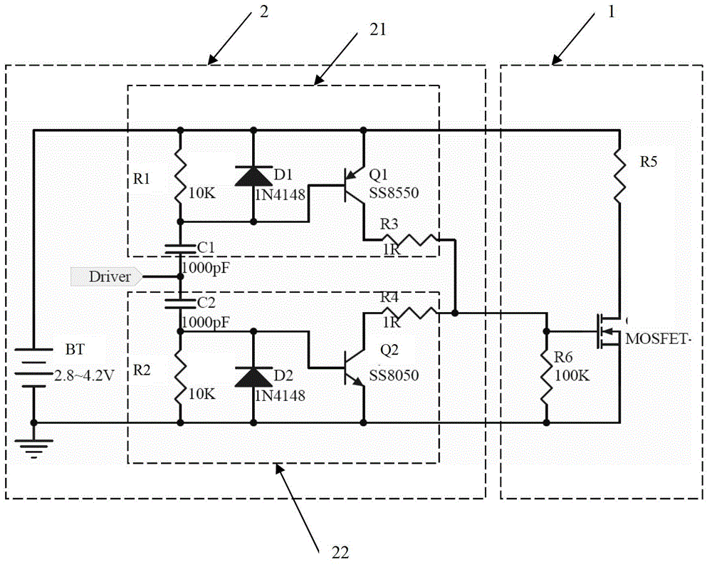
[0028] Such as figure 1 As shown, the drive device of the insulated gate power control device of the present invention includes a drive circuit 2 connected to the insulated gate power control device 1; the insulated gate power control device 1 used in this embodiment includes a MOSFET, resistors R5 and R6 , wherein the resistor R5 is the output load driven by the MOSFET, and R6 is the electrostatic discharge resistor. Of course, the isolated power control device 1 is not limited to this embodiment, for example figure 1 The composition of MOSEFT and resistors R5 and R6, wherein MOSEFT can be IGBT or other insulated gate power control devices; the drive circuit 2 includes a drive power supply BT, a high-side drive circuit 21 and a low-side drive circuit 22, the high-side The drive circuit 21 and the low-variation drive circuit 22 have a symmetrical structure up and down, and the high-side drive circuit 21 includes a first triode Q1, a first capacitor C1, a first diode D1, a firs...

Embodiment 2

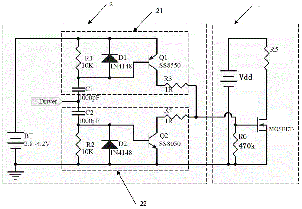
[0037] Such as figure 2 As shown, the difference between the embodiment and the embodiment 1 is only that the MOSFET in the insulated gate control device 1 has an independent working power supply Vdd, the purpose is that the MOSFET is not subject to any limitation of the driving power supply BT, so that the entire circuit The adaptability is wider.


PUM


Abstract

The embodiment of the invention discloses a drive unit of an insulated gate power control device. The drive unit comprises a drive circuit connected with the insulated gate power control device. The drive circuit includes a drive power supply, a high-side drive loop for controlling pull-up driving of the insulated gate power control device, and a low-side drive loop for controlling pull-down driving of the insulated gate power control device. According to the invention, the drive unit has characteristics of low working voltage, high power supply efficiency, low cost, high driving current, fast speed, simple circuit, high reliability, easy integration, and convenient promotion.

Description

technical field [0001] The invention relates to the application of an insulated gate voltage control device, in particular to a driving device for an insulated gate power control device. Background technique [0002] Switching power supply technology has developed rapidly in recent years, and insulating gate voltage control devices such as MOSFETs and IGBTs have been widely used. However, all voltage control devices need to be driven by higher voltage and pulse current than traditional transistors in order to achieve fast turn-on and turn-off. In recent years, engineers around the world have developed hundreds of drive circuits, but the most typical one is to use MOSFET as an insulated gate voltage control device. Its control characteristics can be equivalent to two series-connected inter-electrode capacitances Cgs and Cgd, and The control terminal is the intermediate connection point of the two capacitors. If the voltage at the output terminal of the drain D of the MOSFET ...

Claims


Application Information

Patent Timeline
IPC IPC(8): H03K17/567
Inventor 郑伟伟陈小源
Owner SUNWODA ELECTRONICS
Why Eureka
Try Eureka