Machining device of graphite heater

A graphite heater and processing equipment technology, applied in metal processing equipment, milling machine equipment, details of milling machine equipment, etc., can solve problems such as inconsistent command and action, difficult processing operation, operator falling, etc., to eliminate unsafe factors , The equipment is compact in structure and the effect of reducing the load

Active Publication Date: 2014-09-17
烟台美尔森石墨有限公司
View PDF6 Cites 3 Cited by
  • Summary
  • Abstract
  • Description
  • Claims
  • Application Information

AI Technical Summary

Problems solved by technology

Since the product to be processed is cylindrical, with a height of about one meter and an outer diameter of about one meter, and vertical grooves must be filled up and down in one circle, it is very difficult to process on an ordinary horizontal milling machine because the ordinary horizontal milling machine workbench It is relatively high, and adopts a lifting table or spindle lifting structure. When operating, first squat on the workbench to set the tool, and it also has to move up and down during the processing. Frequently, the operator falls or the product is scrapped. Not only the work efficiency is low, but also high scrap rate
On the other hand, because the machine tool and the workpiece are high, one person cannot complete the entire processing process. Someone needs to operate the machine tool exclusively, and another person watches the processing progress and directs the operation on it. There are often problems that the product is scrapped due to inconsistent command and action.

Method used


Image

  • Machining device of graphite heater
  • Machining device of graphite heater

Examples


Embodiment Construction

[0021] The present invention will be further described below in conjunction with the accompanying drawings and examples.

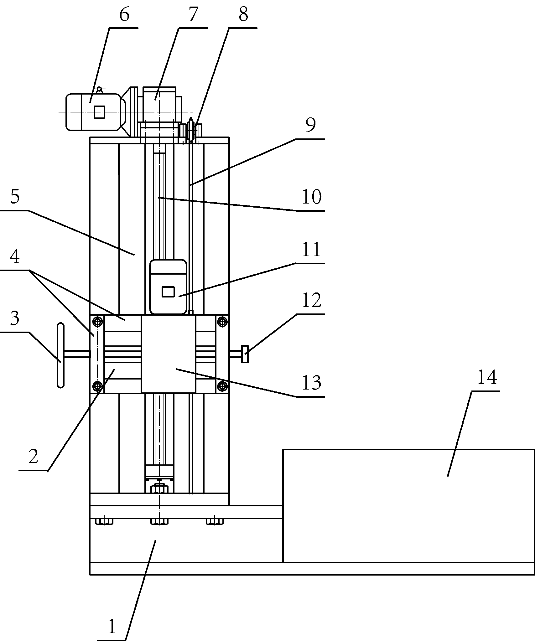
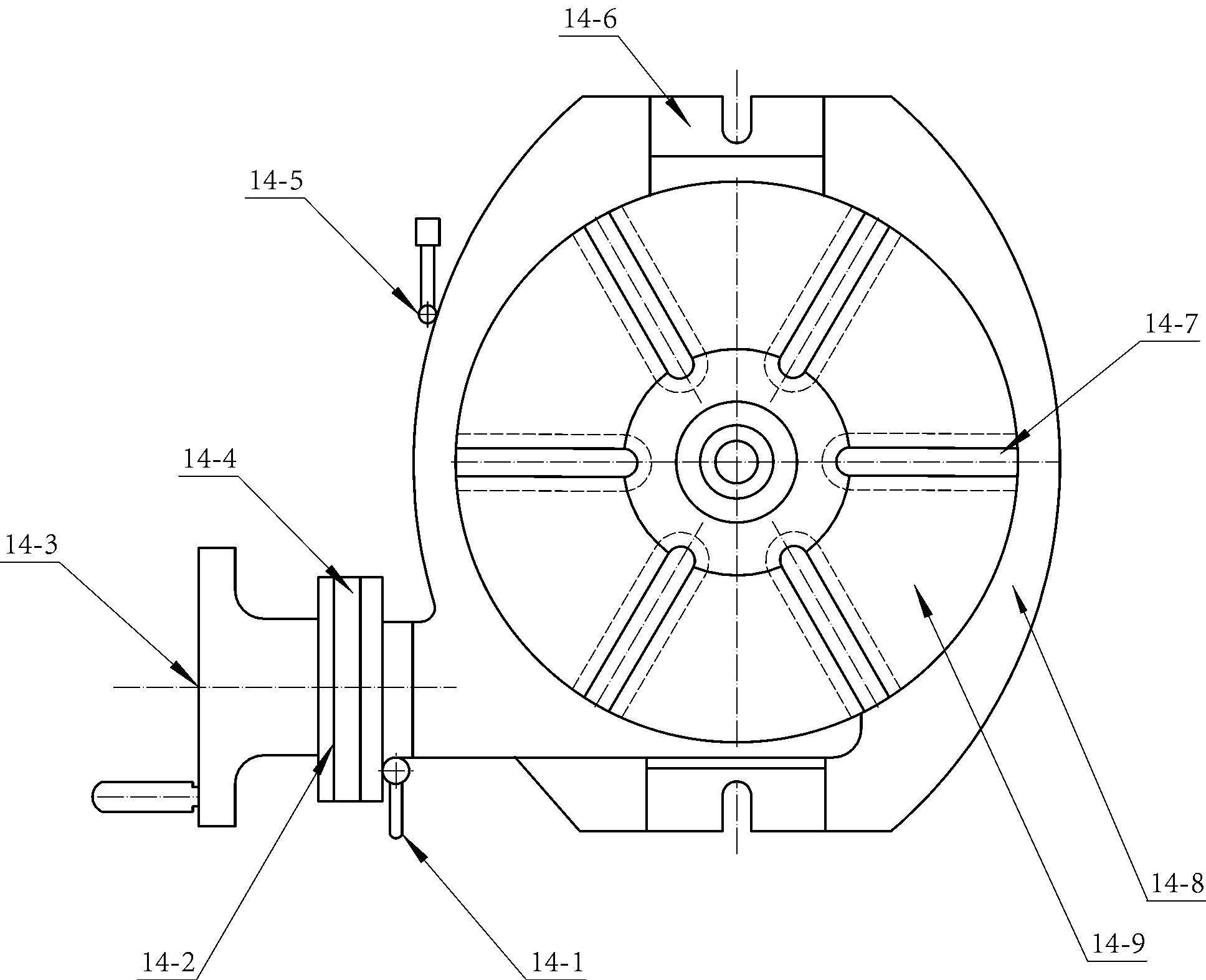
[0022] The present invention includes a knife feeding mechanism and a rotary table 14 used in conjunction with each other.

[0023] Such as figure 1 As shown, the feed mechanism includes a frame 1 with a column 5 installed and a lifting platform 4 slidably installed on the column 5 . The lifting platform 4 includes a middle plate and longitudinal left side plates and longitudinal right side plates respectively located at the left and right ends of the middle plate. A transverse sliding rail 2 positioned in front of the middle board and running parallel to the middle board is installed between the longitudinal left side board and the longitudinal right side board. It also includes a reducer 13 and a main motor 11 connected to the upper end of the reducer 13 through a flange, and the input shaft of the reducer 13 is connected with the motor shaft of the ma...


PUM


Abstract

The invention discloses a machining device of a graphite heater. The machining device comprises a tool feeding mechanism and a slewing workbench which are matched in use, wherein the tool feeding mechanism comprises a rack and a lifting platform; a vertical column is arranged on the rack; the lifting platform is arranged on the vertical column in a sliding manner; a transverse sliding rail is arranged on the lifting platform; the machining device also comprises a speed reducer and a primary motor which is connected on the upper end of the speed reducer and is connected with the speed reducer; a rear side shell of the speed reducer is arranged on the transverse sliding rail in a sliding manner; the machining device further comprises a tool feeding screw rod the inner end of which is connected with the shell of the speed reducer and at the outer end of which a tool feeding hand wheel is arranged; the outer end of the output shaft of the speed reducer is connected with a tool head; the machining device further comprises a screw rod which longitudinally penetrates through the lifting platform and is in screw thread fit with the lifting platform; and a worm gear is connected on the upper end of the screw rod. According to the machining device of the graphite heater, a bar tool is driven to stably feed and lift within a relative large range, the requirement that longitudinal heating grooves are formed in the cylindrical graphite heater is met; and an operator can intuitively observe the machining track of a milling cutter, thus the operation quality is guaranteed and the defective rate is lowered.

Description

[0001] technical field [0002] The invention relates to a knife feeding mechanism for processing graphite heaters. Background technique [0003] Due to the outstanding advantages of uniform heating, low energy consumption, and high thermal efficiency, graphite heaters for single crystal furnaces have been widely used. At present, the equipment used to process cylindrical graphite heaters is generally an ordinary horizontal milling machine. Since the product to be processed is cylindrical, with a height of about one meter and an outer diameter of about one meter, and vertical grooves must be filled up and down in one circle, it is very difficult to process on an ordinary horizontal milling machine because the ordinary horizontal milling machine workbench It is relatively high, and adopts a lifting table or spindle lifting structure. When operating, first squat on the workbench to set the tool, and it also has to move up and down during the processing. Frequently, the operat...

Claims


Application Information

Patent Timeline
Patent Type & Authority Applications(China)
IPC IPC(8): B23C3/00B23Q5/40B23Q1/26
Inventor 历福江刘祥庆王宇姜庆波
Owner 烟台美尔森石墨有限公司
Why Eureka
Try Eureka