Plasma device for production of metal powder

A metal powder, plasma technology, applied in the direction of plasma, electrothermal device, chemical/physical/physical-chemical process of applying energy, etc., can solve the problems of insufficient, reduced metal vapor, slowed carrier gas flow rate, etc., to achieve particle size Narrow distribution of effects

Active Publication Date: 2014-09-24
SHOEI CHEM IND CO LTD
View PDF7 Cites 4 Cited by
  • Summary
  • Abstract
  • Description
  • Claims
  • Application Information

AI Technical Summary

Problems solved by technology

This is considered to be because the concentration (density) of the metal vapor contained in the carrier gas in the indirect cooling region 34 is lowered, so nucleation cannot be sufficiently generated in the indirect cooling region 34.
And it can be seen that since the flow velocity of the carrier gas becomes slow, there will also be a new problem that the newly precipitated nuclei are easily attached to the inner wall of the inner tube 36.

Method used


Image

  • Plasma device for production of metal powder
  • Plasma device for production of metal powder
  • Plasma device for production of metal powder

Examples


Embodiment 1

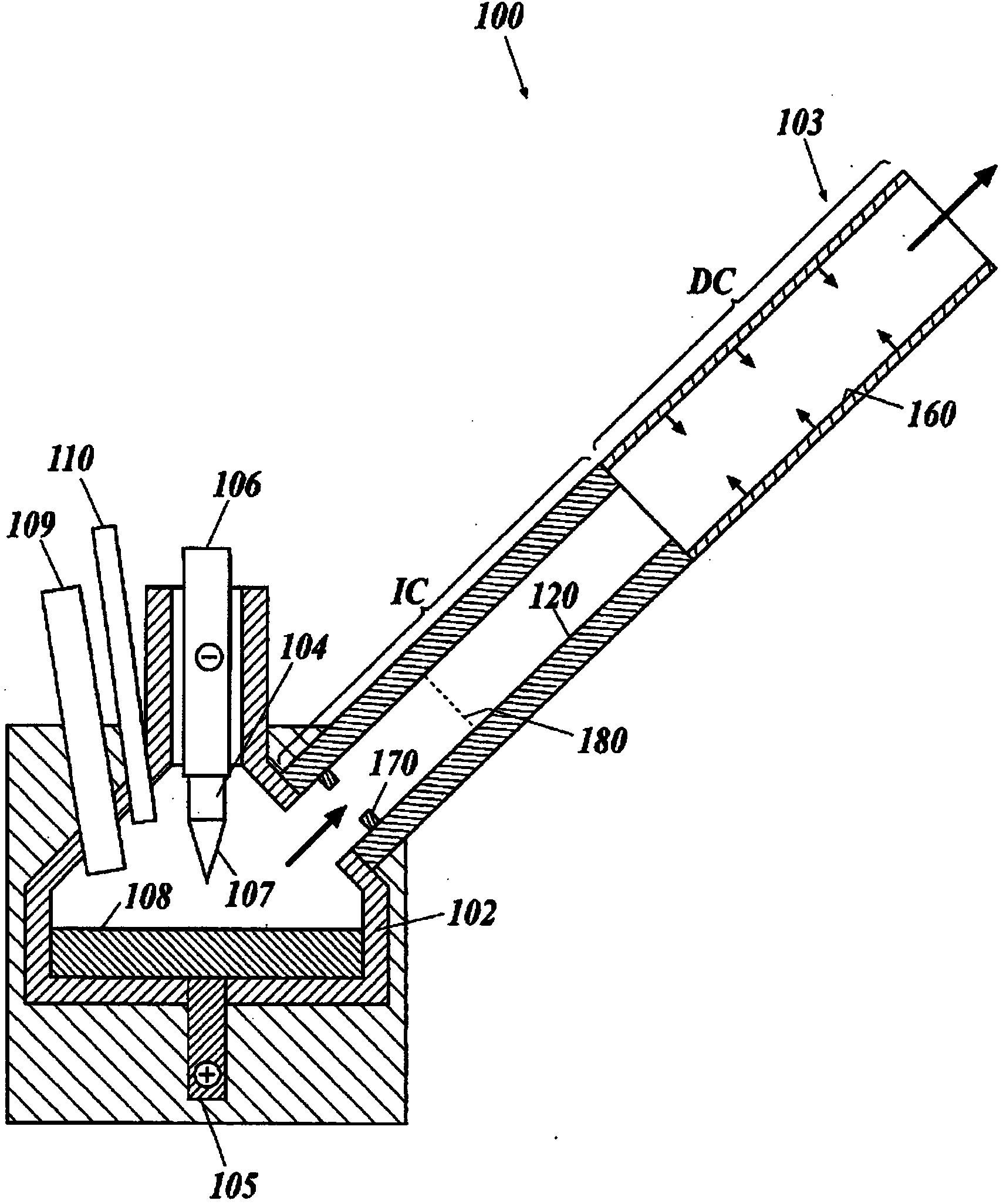
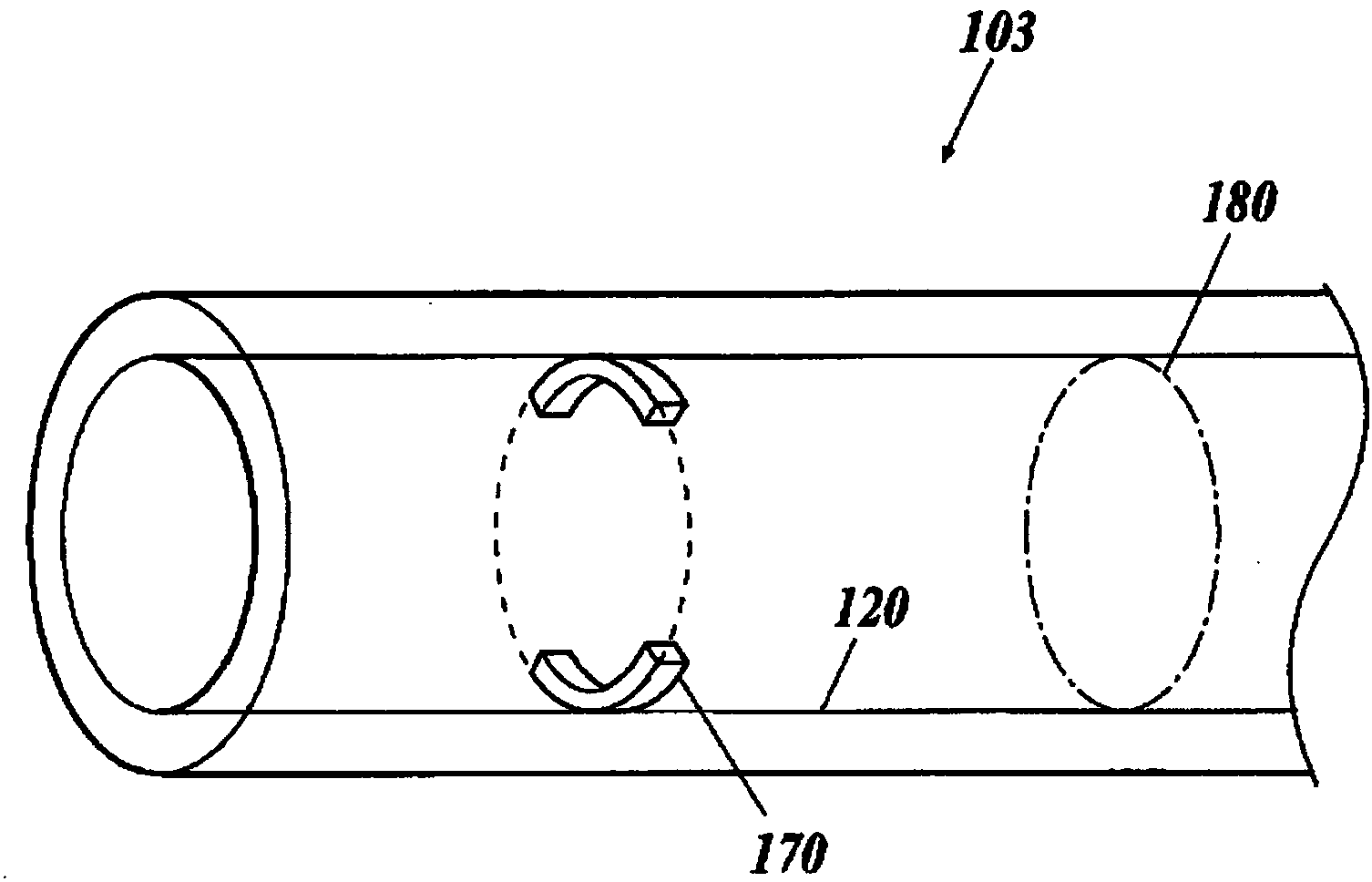
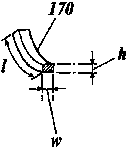
[0071] use Figure 2A and Figure 2B The cooling pipe 103 provided with the convex portion 170 described in figure 1 The described plasma apparatus 100 produces nickel powder. The cooling pipe 103 is a cooling pipe formed by combining an inner pipe 120 (indirect cooling area IC) with an inner diameter of 8 cm and a length of 115 cm and an inner pipe 160 (direct cooling area DC) with an inner diameter of 18 cm and a length of 60 cm. The inner wall of the tube 120 is provided with two convex portions 170 with a height (h) of 1 cm, a width (w) of 1 cm, and a length (l) of 5 cm at a position 20 cm away from the upstream end of the inner tube 120.

[0072] Controlled so that the carrier gas passing through the cooling pipe 103 passes 300L per minute, and the metal concentration is 2.1~14.5g / m 3 Range.

[0073] For the obtained nickel powder, the cumulative percentage 10% value, 50% value, and 90% value (hereinafter referred to as "D10", "D50", and "D90", respectively, based on the weig...

Embodiment 2

[0079] In addition to using Figure 5A and Figure 5B Except for the cooling pipe 103 provided with the convex portion 173 described, nickel powder was produced in the same manner as in Example 1. As the convex part 173, the cross section was a substantially equilateral triangle shape with a base (w) of 1 cm and a height (h) of 1 cm, and a plurality of squares with a length (l) of 3 cm were prepared. Furthermore, on the inner wall of the inner tube 120, a plurality of protrusions 173 span the entire area of ​​the indirect cooling area IC so that the longitudinal direction of the protrusion 173 is at an angle of 45° with respect to the longitudinal direction (axial direction) of the cooling tube 103 Arranged into two spirals.

[0080] The nickel powder obtained in Example 2 is a powder with a narrow particle size distribution such as D50=0.44 μm and SD=1.10.

[0081] Based on the above results, compared with the nickel powder obtained in Comparative Example 1, the nickel powder obt...


PUM


Abstract

A plasma device which is provided with: a reaction container to which a metal starting material is supplied; a plasma torch which generates plasma between itself and the metal starting material within the reaction container, thereby evaporating the metal starting material and producing a metal vapor; a carrier gas supply unit which supplies, into the reaction container, a carrier gas for conveying the metal vapor; and a cooling tube which cools the metal vapor that is conveyed from the reaction container by the carrier gas, thereby producing a metal powder. The cooling tube is provided with: an indirect cooling section for indirectly cooling the metal vapor that is conveyed from the reaction container by the carrier gas and/or the metal powder; and a direct cooling section for directly cooling the metal vapor and/or the metal powder, said direct cooling section being continued to the indirect cooling section. At least a part of the inner wall of the indirect cooling section is provided with projections and/or recesses.

Description

Technical field [0001] The present invention relates to a plasma device for producing metal powder, and more particularly to a plasma device that is provided with a tubular cooling tube and uses the cooling tube to cool metal vapor generated by melting and evaporating a metal raw material to produce metal powder. Background technique [0002] In the manufacture of electronic components such as electronic circuits or wiring boards, resistors, capacitors, and IC packages, conductive metal powders are used to form conductive coatings or electrodes. The characteristics and properties required of this metal powder include the following: less impurities; fine powder with an average particle size of about 0.01 to 10 μm; making the particle shape and particle size uniform; less agglomeration; dispersion in paste Good properties; good crystallinity, etc. [0003] In recent years, along with the miniaturization of electronic components and wiring boards, thinner layers and finer pitches of ...

Claims


Application Information

Patent Timeline
Patent Type & Authority Applications(China)
IPC IPC(8): B22F9/14B01J19/08H05B7/18H05H1/32
CPCB01J2219/0871C22C19/03B22F9/12B22F9/14B01J19/088B22F2202/13H05H1/48H05H1/32B01J2219/0879H05B7/18H05H1/28
Inventor 清水史幸前川雅之川口周作
Owner SHOEI CHEM IND CO LTD
Why Eureka
Try Eureka