Flexible metal clad laminate and preparation method thereof
A flexible metal and manufacturing method technology, applied in the direction of metal layered products, chemical instruments and methods, and manufacturing printed circuit precursors, can solve the problem of low adhesion, achieve excellent adhesion and dimensional stability, and inhibit The effect of poor appearance problems
- Summary
- Abstract
- Description
- Claims
- Application Information
AI Technical Summary
Problems solved by technology
Method used
Image

Examples
Synthetic example 1
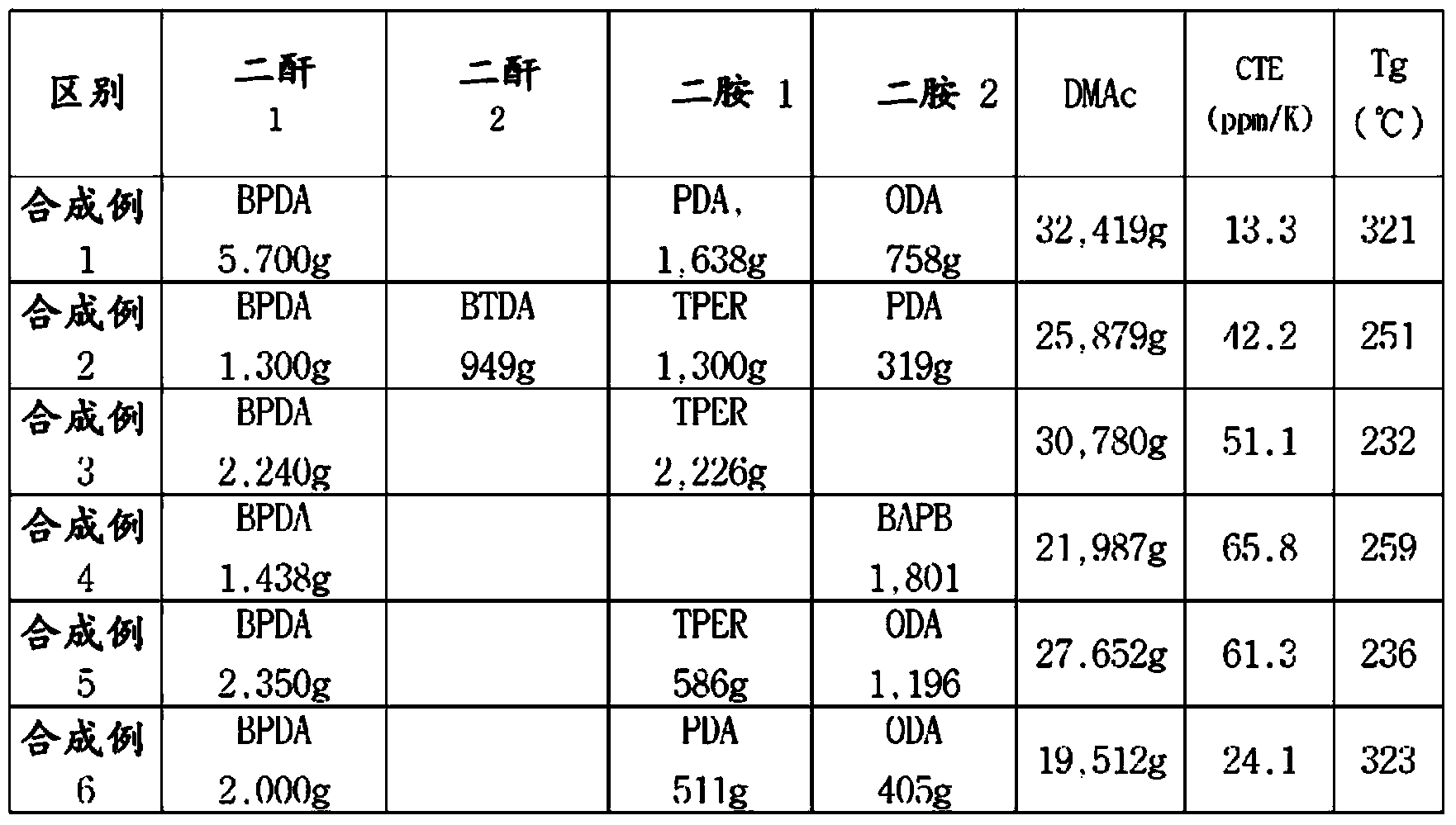
[0122] With the contents in Table 1, 1638 g of PDA and 758 g of diamine of ODA were stirred and completely dissolved in 32416 g of DMAc solution under a nitrogen atmosphere, and then 5700 g of BPDA was added in fractions as dianhydride. Thereafter, stirring was continued for about 24 hours, thereby preparing a polyamic acid solution. After casting (casting) the polyamic acid solution prepared in this way into a film with a thickness of 20 μm, the temperature was raised to 350° C. over 60 minutes and maintained for 30 minutes to cure. The measured linear thermal expansion coefficient and glass transition temperature were 13.3 ppm / K and 321° C., respectively.
Synthetic example 2
[0123] Synthesis Example 2 to Synthesis Example 3
[0124] It was prepared by the same method as Synthesis Example 1 using the composition and content in Table 1, and Table 1 shows the measured linear thermal expansion coefficient and glass transition temperature.
[0125] Table 1. Composition of polyamic acid solution and linear thermal expansion coefficient and glass transition temperature after complete imidization
[0126]
Embodiment 1
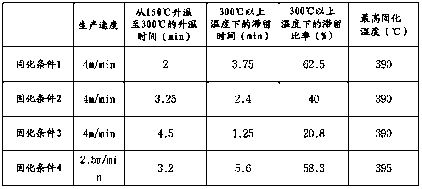
[0128] After coating the polyamic acid solution prepared in Synthesis Example 2 on an electrolytic copper foil (roughness Rz = 2.0 μm) with a thickness of 12 μm so that the final cured thickness becomes 4 μm, it was dried at 130° C. A first polyimide precursor layer was formed. The polyamic acid solution prepared in Synthesis Example 1 was coated on one side of the first polyimide precursor layer so that the final cured thickness was 13 μm, and then dried at 150° C. to form the second polyimide precursor layer. Polyimide precursor layer. After that, the thermoplastic polyamic acid solution prepared in Synthesis Example 3 was coated on one side of the second polyimide precursor layer so that the thickness after final curing was 3.5 μm, and then dried at 150° C. to form A third polyimide precursor layer was formed. The multi-layer polyimide precursor layer on the copper foil produced in this way was completely imidized according to the curing condition 1 in Table 2 by using an...
PUM
| Property | Measurement | Unit |
|---|---|---|
| Glass transition temperature | aaaaa | aaaaa |
| Coefficient of linear thermal expansion | aaaaa | aaaaa |
| Glass transition temperature | aaaaa | aaaaa |
Abstract
Description
Claims
Application Information
 - R&D
- Intellectual Property
- Life Sciences
- Materials
- Tech Scout
- Unparalleled Data Quality
- Higher Quality Content
- 60% Fewer Hallucinations
Browse by: Latest US Patents, China's latest patents, Technical Efficacy Thesaurus, Application Domain, Technology Topic, Popular Technical Reports.
© 2025 PatSnap. All rights reserved.Legal|Privacy policy|Modern Slavery Act Transparency Statement|Sitemap|About US| Contact US: help@patsnap.com