Circulation drying device for water-containing solid material

A solid material, cycle drying technology, applied in the direction of drying solid material, non-progressive dryer, drying, etc., can solve the problem of not reaching the drying level

Inactive Publication Date: 2014-10-01
BEIJING XURI QINGFENG SCI & TECH
View PDF2 Cites 6 Cited by
  • Summary
  • Abstract
  • Description
  • Claims
  • Application Information

AI Technical Summary

Problems solved by technology

For solid materials with high water content or a large amount of solid ma

Method used


Image

  • Circulation drying device for water-containing solid material
  • Circulation drying device for water-containing solid material
  • Circulation drying device for water-containing solid material

Examples


Embodiment 1

[0067] Embodiment 1. Micro-flush toilet and excrement in-situ processor

[0068] In this example, the aqueous solid material is feces. Wherein feces refers to stool and / or urine. Of course, the feces are not limited to human feces, and may also be animal feces, such as animal feces from poultry farms. The water-containing solid material circulation drying device of the present invention is used as an in-situ processor of feces.

[0069] Its workflow is:

[0070] 1. Feces are discharged into the micro-flush toilet. The toilet can be directly connected to the feed port Mx of the circulation drying device of the present invention, so only a small amount of water is needed to directly send the excrement into the circulation drying device. For example, the The toilet is flushed by pressure spray water mist, which greatly saves the flushing water; the mixture of feces / urine / flush water is sucked by the sewage pump RSP with crushing cutter head (to prevent clogging), and is added ...

Embodiment 2

[0076] Example 2. Kitchen waste treatment device

[0077] Kitchen waste is a difficult part of domestic waste. It has a high content of organic matter, breeds bacteria, produces peculiar smell, and is mixed with other recyclable waste, which increases the difficulty of subsequent sorting and treatment.

[0078] Utilize application example 1 of the present invention, and feed inlet Mx wherein is connected to a pulverizer, kitchen waste-leftovers, etc. are pulverized as water-containing solid materials to be dried and mixed with carrier balls, and the rest are processed The steps are the same as in Example 1, and then the kitchen waste can be dried and converted into sterilized organic fertilizers.

Embodiment 3

[0079] Embodiment 3. the processing of all the other aqueous solid materials

[0080] Obviously, the water-containing solid materials to be dried are not limited to feces and kitchen waste, but can also be livestock waste from farms, sludge from sewage treatment tanks, lake sludge, waste residue from the food fermentation industry, and Chinese herbal medicines after extracting active ingredients. Waste slag, etc., all can utilize device and method of the present invention to handle.


PUM


Abstract

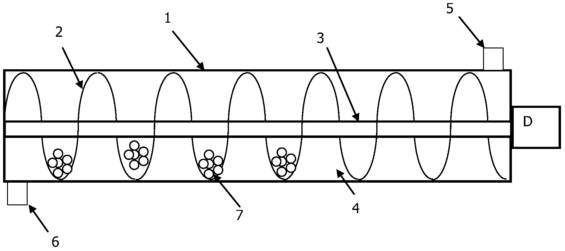
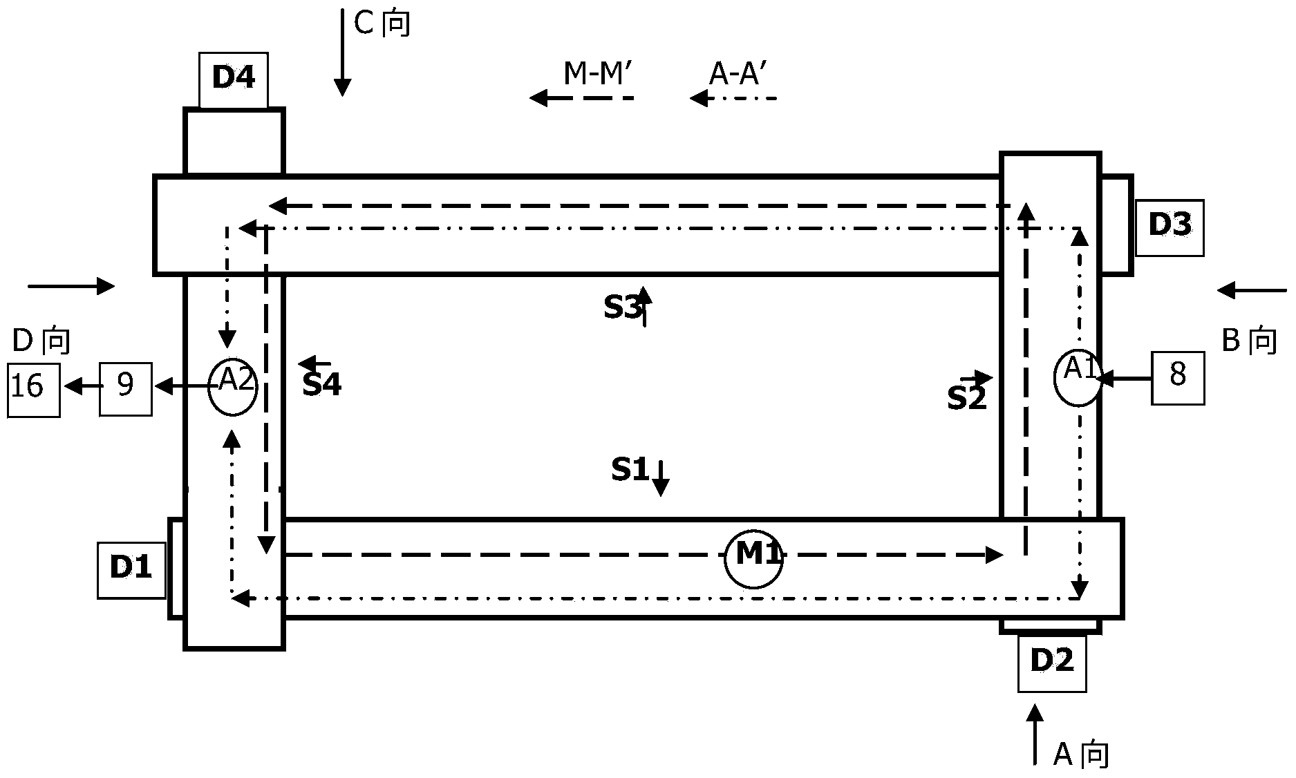
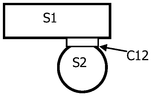
The invention relates to a circulation drying device for a water-containing solid material. The circulation drying device comprises N screw conveying dryers and a screening and discharging screw S (N+1), wherein the N screw conveying dryers S1-SN form a closed-loop channel; a discharging port 15 communicated with the screening and discharging screw S (N+1) is formed in the bottom of the front end of the Nth screw conveying dryer SN, and a drive deice of the Nth screw conveying dryer SN can rotate in forward and reverse directions; Y small holes or grooves are formed in the bottom of a casing of the screening and discharging screw S (N+1), the top of the front end of the screening and discharging screw S (N+1) is communicated with the discharging port 15 of the Nth screw conveying dryer SN, and the bottom of the rear end of the screening and discharging screw S (N+1) is communicated with a material inlet of the first screw conveying dryer S1; and when Dn rotates in the forward direction, a drive device of the screening and discharging screw S (N+1) does not rotate, when Dn rotates in the reverse direction, the drive device of the screening and discharging screw S (N+1) rotates in the forward direction, dry powder after drying is blanked from the small holes or grooves in the bottom of the casing, and carrying balls return to the S1.

Description

technical field [0001] The invention belongs to the field of drying equipment or evaporation equipment. Background technique [0002] The "water-containing solid material" involved in the present invention includes liquid materials with low solid content and high fluidity, such as seawater, municipal landfill leachate, etc.; it also includes viscous materials with high solid content and low fluidity, such as feces, Silt etc. [0003] For a long time, the evaporation / drying industry in the industry has faced a difficult problem in the methods and equipment for evaporating or drying aqueous solid materials (also known as wet materials or materials to be dried). That is, evaporation / drying is an energy-intensive process, and appropriate methods are required to reduce energy consumption. [0004] Generally speaking, there are two methods for drying water-containing materials (also known as wet materials or materials to be dried). The first is forced evaporation, that is, heat...

Claims


Application Information

Patent Timeline
IPC IPC(8): F26B11/14F26B25/04F26B25/00
Inventor 宁静王磊苏徐何增涛陈峰
Owner BEIJING XURI QINGFENG SCI & TECH
Why Eureka
Try Eureka