
Visual detecting method and device based on decoupling detection for circular seams

A visual detection device and visual detection technology, applied in the direction of measuring devices, optical devices, instruments, etc., can solve problems affecting the real-time performance of the system, inaccurate center position, inaccurate deviation, etc., to avoid camera imaging models and reduce requirements , to avoid the effect of matrix transformation

Active Publication Date: 2014-10-08
HEBEI UNIV OF TECH
View PDF6 Cites 41 Cited by
  • Summary
  • Abstract
  • Description
  • Claims
  • Application Information

AI Technical Summary

Problems solved by technology

In the general camera calibration process, the internal and external parameters of the camera are often determined first. The internal parameters of the camera only need to be calibrated once, but the external parameters need to change from time to time with the rotation of the weldment, which is not easy to calibrate, and the amount of calculation is large.
Binocular vision needs to fuse the information obtained by the two cameras when obtaining the three-dimensional information of the weld, which has a large amount of calculation and affects the real-time performance of the system
[0003] Chinese patent CN101954557 discloses a two-dimensional position information extraction method for structured light weld seam image tracking. The method uses a structured light image weld seam tracking sensor to obtain the weld seam image, and the sensor processes the image to obtain the weld seam image. The center position directly provides the left and right deviation information of the weld seam for seam tracking; at the same time, using the geometric position relationship between the sensor and the welding workpiece, the real-time obtained previous frame image is compared with the next frame, and the height direction of the welding torch is obtained. The amount of variation can provide information on the height deviation of the welding torch. The disadvantage is that the center position of the current frame image captured by the camera will be inaccurate due to the influence of light, arc light, reflection, splash and other factors during the welding process. Comparing frame images will make the deviation more and more inaccurate

Method used


Image

  • Visual detecting method and device based on decoupling detection for circular seams
  • Visual detecting method and device based on decoupling detection for circular seams
  • Visual detecting method and device based on decoupling detection for circular seams

Examples


Embodiment 1

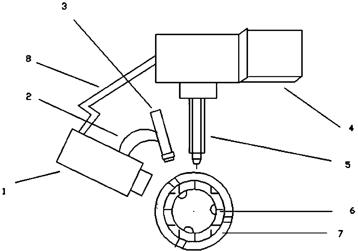
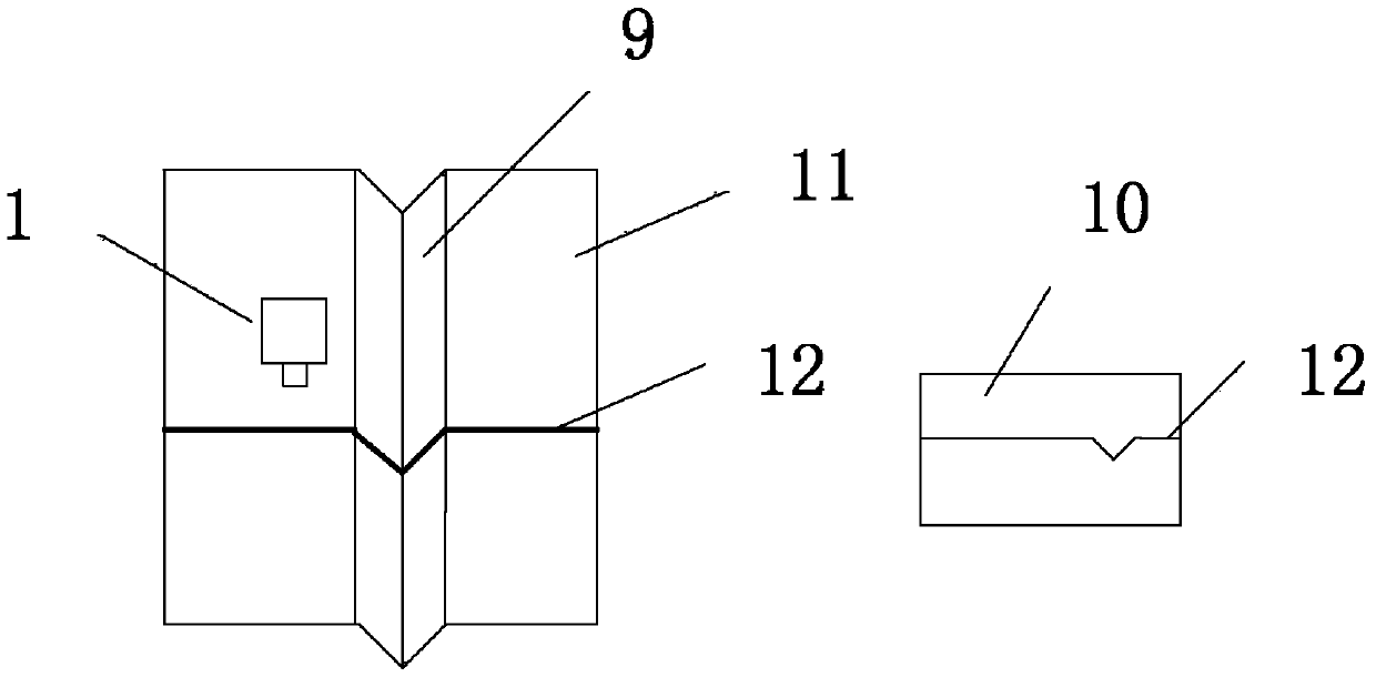
[0106] In this embodiment, the device is connected according to the requirements, and the outer diameter of the V-shaped groove annular weldment is selected to be 195mm, the groove width is 14mm, and the groove depth is 7mm.

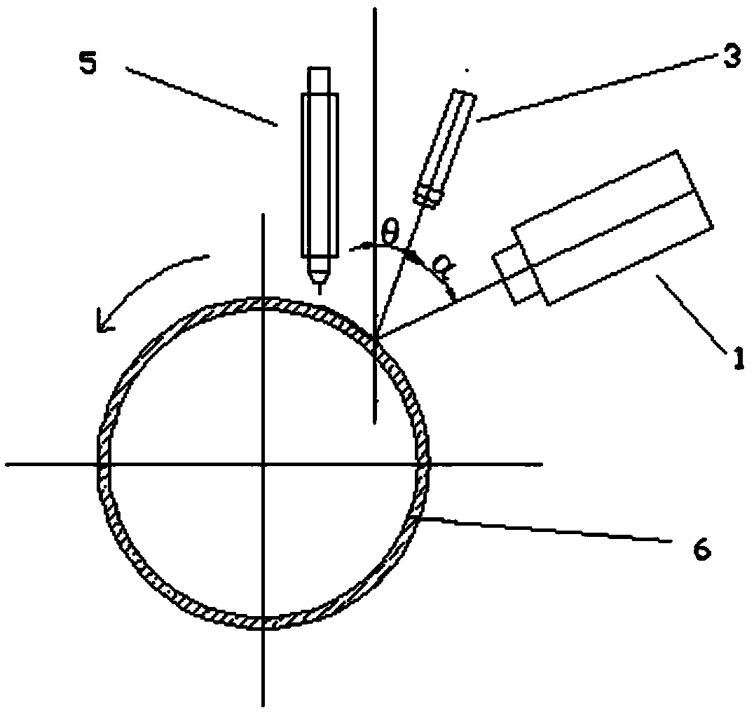
[0107] First turn on the power of the camera, move the welding torch to the initial welding position, and at the same time camera 1 collects and processes images to obtain the weld image coordinates and weld position information, record the reference image coordinates of the initial feature points of the weld, and start welding automatically after completion tracking function. In the process of automatic welding seam tracking, the image coordinates of the welding seam are extracted once in each sampling period as the feedback value of the current welding seam position, and the actual deviation in the two directions of the welding torch 5 is directly calculated through the decoupling detection algorithm based on the image plane.

[0108] The visual inspec...


PUM

PropertyMeasurementUnit
diameteraaaaaaaaaa

Abstract

The invention relates to a visual detecting method based on decoupling detection for circular seams. The method is used for detecting, recognizing and welding the welding seams of circular welding pieces with V-shaped grooves. The method is characterized by comprising the following steps: first, processing pictures and extracting features; and second, decoupling image information. For the method, according to the three-dimensional welding seam feature information extracted by decoupling single frame images, the deviation value of a welding gun in a two-dimensional plane relative to the welding seam center can be calculated, the accurate positioning of welding spots in three-dimensional space can be realized, the decoupling algorithm is performed by monocular vision when the two-dimensional welding seam information is obtained, the tedious matrix transformation when the welding seam information is demarcated is avoided, the demarcating and calculating time is greatly saved, and the real-time performance of a system is obviously improved. On one hand, building a complex imaging model of a camera is avoided, and on the other hand, the demarcating precision, the robustness and the applicability of the camera are improved.

Description

technical field [0001] The invention relates to a detection method and positioning for determining the position of a welding spot in a circular seam, in particular to a visual detection method and device for a circular seam based on decoupling detection. Background technique [0002] With the increasing requirements of modern welding production on product quality and production efficiency, how to ensure the welding quality and improve the level of welding automation has become a major issue in front of people. The working environment of the welding process is very harsh for the vision system of the welding robot. For example, the welding work inevitably has a lot of interference such as arc light, spatter, smoke and dust; The multiple reflections of the workpiece present irregular reflection interference; the surface of the workpiece is sometimes irregular, and there are often traces of iron filings, oil stains, chalk marks, etc.; the welds of the workpiece have different sh...

Claims


Application Information

Patent Timeline
Patent Type & Authority Applications(China)
IPC IPC(8): B23K9/028B23K9/127B23K9/32G01B11/00
CPCB23K9/028B23K9/1274
Inventor 陈海永王萌马子涵孙鹤旭
Owner HEBEI UNIV OF TECH
Learn More