Mobile terminal wireless power supply system

A wireless power supply, mobile terminal technology, applied in the direction of electromagnetic wave systems, electrical components, circuit devices, etc., can solve the problem of unresolved energy electromagnetic wave source issues such as transmitters and receivers

Active Publication Date: 2015-12-09
长春市奥霏办公设备有限公司
View PDF7 Cites 0 Cited by
  • Summary
  • Abstract
  • Description
  • Claims
  • Application Information

AI Technical Summary

Problems solved by technology

This non-contact charging method can no longer meet people's needs, and in recent years, wireless power supply methods based on electromagnetic waves have become a research hotspot.
[0004] However, in the current published literature, there is no prior art that provides a complete solution from the emission of energy electromagnetic waves to the reception and use. The prior art closest to the present invention is the invention patent "Wireless Power Supply for Mobile Terminals" with application number 201310544227.8 Device", the patent discloses a wireless power supply device, the structure of which includes a receiving antenna, a rectifier circuit, a protection circuit, an energy storage device and a power management circuit, which can convert electromagnetic waves received by the receiving antenna into direct current for charging mobile terminals , but the patent does not solve the problem of the source of the energy electromagnetic wave that can be received by the device and how to carry out matching transmission between the transmitting end and the receiving end.

Method used


Image

  • Mobile terminal wireless power supply system
  • Mobile terminal wireless power supply system
  • Mobile terminal wireless power supply system

Examples


Embodiment 1

[0042] Embodiment 1 The overall structure of the system of the present invention

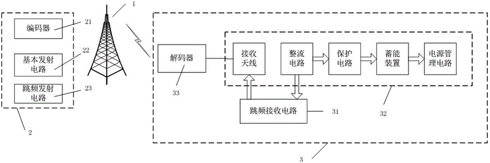
[0043] see figure 1 , the structure of the present invention includes: transmitting antenna 1, wireless energy transmitter 2, wireless energy receiving device 3;

[0044] The transmitting antenna is used to transmit energy electromagnetic waves;

[0045] The wireless energy transmitter 2 is used to generate energy electromagnetic waves for the transmitting antenna 1 to emit outwards, and its structure includes an encoder 21, a basic transmitting circuit 22 and a frequency hopping transmitting circuit 23, wherein the output terminals C_OUT and The transmitting antenna 1 is connected, the output terminal S_OUT of the frequency hopping transmitting circuit 23 is connected with the input terminal B_IN of the basic transmitting circuit 22, and the output terminal B_OUT of the basic transmitting circuit 22 is connected with the transmitting antenna 1; the structure of the frequency hopping transmitti...

Embodiment 2

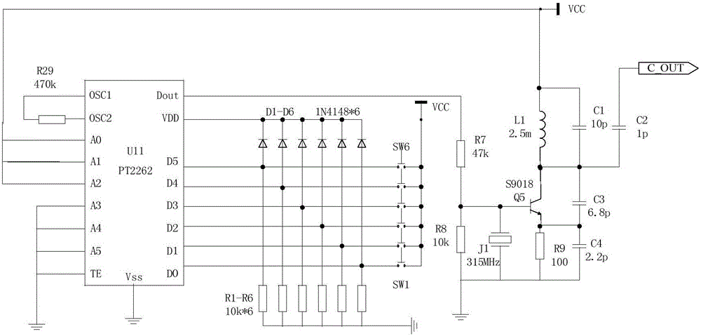
[0047] Embodiment 2 Encoder circuit

[0048] refer to figure 2 , the structure of the encoder 21 is that the resistor R29 is connected between pin 15 and pin 1 of the PT2362 chip U11, pins 1 to 3 of the PT2362 chip U11 are connected to the power supply VCC, pins 4 to 6 are grounded, pins 7 and 8 are Pins 10 to 13 are connected to one end of resistors R1 to R6 in turn, and are connected to one end of switches SW1 to SW6 in turn, and connected to anodes of diodes D1 to D6 in turn, and the other ends of resistors R1 to R6 are grounded. , the other ends of the switches SW1~SW6 are all connected to the power supply VCC, the cathodes of the diodes D1~D6 are connected to the 18 pins of the PT2362 chip U11, the 17 pins of the PT2362 chip U11 are connected to one end of the resistor R7, and the other end of the resistor R7 is connected to the base of the transistor Q5 It is also connected to one end of the resistor R8 and one end of the crystal oscillator J1 with a frequency of 315MH...

Embodiment 3

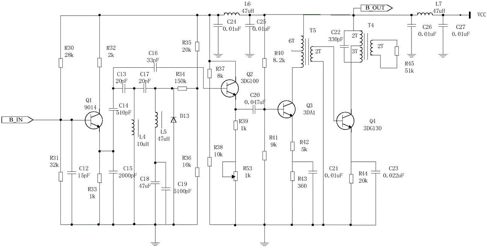
[0050] Embodiment 3 Basic transmitting circuit

[0051] refer to image 3 , the structure of the basic transmitting circuit 22 is that the base of the triode Q1 is connected to one end of the resistor R30, one end of the resistor R31 and one end of the capacitor C12, the other end of the resistor R32 and the other end of the capacitor C12 are grounded, and the other end of the resistor R30 One end is connected to the collector of transistor Q1, the emitter of transistor Q1 is connected to capacitors C14, C15 and one end of resistor R33, the other end of capacitor C15 and resistor R33 is grounded, the other end of capacitor C14 is connected to one end of capacitors C13 and C16, capacitor C16 The other end of capacitor C13 is connected to the base of transistor Q2, the other end of capacitor C13 is connected to capacitor C17 and one end of inductor L4, the other end of inductor L4 is grounded, the other end of capacitor C17 is connected to inductor L5, one end of resistor R34 an...


PUM


Abstract

The invention belongs to the technical field of wireless communication, in particular to a mobile terminal wireless power supply system. The mobile terminal wireless power supply system structurally comprises a transmitting antenna (1), a wireless energy transmitter (2) and a wireless energy receiving device (3). The wireless energy transmitter (2) comprises an encoder (21), a basic transmitting circuit (22) and a frequency hopping transmitting circuit (23). The wireless energy receiving device (3) comprises a frequency hopping receiving circuit (31), a mobile terminal wireless power supply device (32) and a decoder (33). The mobile terminal wireless power supply system has the advantages of being convenient to use, capable of achieving non-contact-type charging, large in coverage range, strong in anti-jamming capacity, high in safety and the like.

Description

technical field [0001] The invention belongs to the technical field of wireless communication, in particular to a mobile terminal wireless power supply system. Background technique [0002] In the field of communications, with the development of industrial production and science and technology (especially power electronics technology), electrical equipment is becoming more and more popular, and higher requirements are placed on the power supply methods of existing electronic equipment. Since the traditional power supply method basically adopts the transmission method of direct conduction of contact electric energy, and this method has problems such as poor mobility, unsafety, and especially not suitable for harsh environments (underwater, humidity, etc.), it can no longer meet social development. demand. Therefore, based on this problem, a technology that transmits electric energy in a non-electrical direct contact manner, that is, wireless power transfer technology (WPT), ...

Claims


Application Information

Patent Timeline
Patent Type & Authority Patents(China)
IPC IPC(8): H02J17/00H02J50/20
Inventor 于银辉王玉星杨蕾张春海陈登昭
Owner 长春市奥霏办公设备有限公司
Why Eureka
Try Eureka