Carbon nanotube field effect transistor (CNTFET) with peak-symmetric linearity doped structure

A linear doping, field effect transistor technology, applied in the fields of nanotechnology, nanotechnology, nanotechnology for information processing, can solve problems such as device performance degradation, and achieve the effect of large switching current ratio

Inactive Publication Date: 2014-10-15
NANJING UNIV OF POSTS & TELECOMM
View PDF4 Cites 1 Cited by
  • Summary
  • Abstract
  • Description
  • Claims
  • Application Information

AI Technical Summary

Problems solved by technology

However, the bipolar effect of the Schottky carbon CNTFET greatly reduces the performance of the device, which is also the shortcoming of the structure.

Method used


Image

  • Carbon nanotube field effect transistor (CNTFET) with peak-symmetric linearity doped structure
  • Carbon nanotube field effect transistor (CNTFET) with peak-symmetric linearity doped structure
  • Carbon nanotube field effect transistor (CNTFET) with peak-symmetric linearity doped structure

Examples


Embodiment Construction

[0019] The present invention will be further described below in conjunction with specific embodiments and accompanying drawings.

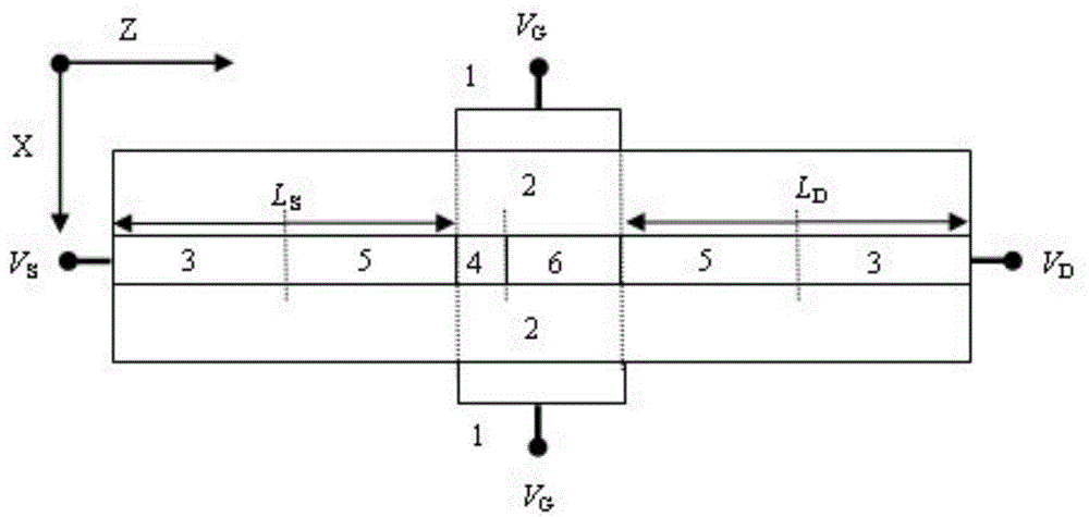
[0020] The carbon nano field effect transistor with peak doping combined with symmetrical linear doping structure of the present invention includes source V s , drain V D , channel, gate oxide 2 and double gate V G Structure, the channel is composed of a carbon nanotube layer, on the carbon nanotube layer from the end near the source to the end near the drain are N-type heavily doped region 3, linear doping structure 5, peak doping Structure 4, intrinsic carbon nanotube 6, linear doping structure 5, N-type heavily doped region 3; gate oxide layer 2 is located on both sides of the carbon nanotube layer, and gate 1 is provided on the outside of the two gate oxide layers 2 A double gate structure is formed.

[0021] The double gate structure is two gates 1 symmetrical to the channel, and the two gates 1 are filled with the same dielectric material....


PUM


Abstract

The invention discloses a carbon nanotube field effect transistor (CNTFET) with a peak-symmetric linearity doped structure. A transportation model applicable to the CNTFET with the peak-symmetric linearity doped structure is constructed, and by means of the model, the influence of a HALO-Linear doping strategy on electrical properties of the CNTFET is analyzed and calculated. Through contrastive analysis of electrical properties of CNTFETs using other doping strategies, the CNTFET with the peak-symmetric linearity doped structure has a higher switched current ratio, lower leakage current, a smaller subthreshold amplitude, higher cut-off frequency and shorter delay time, that is, the CNTFET using the HALO-Linear doping strategy has better grid-control capacity and better switching characteristics and is capable of effectively inhibiting a short-channel effect and a hot carrier effect.

Description

technical field [0001] The invention belongs to the field of carbon nanometer field effect tubes, and relates to a carbon nanometer field effect tube with peak-symmetrical linear doping (HALO-Linear) structure. Background technique [0002] With the continuous shrinking of the device size, the performance requirements of the device are getting higher and higher, and people's eyes have shifted to new materials, and one of the most concerned is carbon nanotubes. Carbon nanotubes are tubular structures surrounded by graphene sheets. The origin of the name of carbon nanotubes is that its diameter is very small in the nanometer scale, ranging from a few nanometers to tens of nanometers, and its length is also very small in the order of microns. As the name suggests, the structure of carbon nanotubes, like graphite and diamond, is an allotrope of carbon, that is, a structure composed of carbon hexagons. But the difference is that it is a tubular material, which can be seen as a ...

Claims


Application Information

Patent Timeline
Patent Type & Authority Applications(China)
IPC IPC(8): H01L29/78B82Y10/00
CPCB82Y10/00H01L29/0669H01L29/36H01L29/7831
Inventor 王伟高健张露岳工舒张婷李娜杨晓
Owner NANJING UNIV OF POSTS & TELECOMM
Why Eureka
Try Eureka