Trench type insulated gate field effect transistor and manufacture method thereof

A field effect transistor and manufacturing method technology, applied in semiconductor/solid-state device manufacturing, semiconductor devices, electrical components and other directions, can solve the problems of improving devices, high process difficulty, reducing breakdown voltage of IGBT devices, etc., to improve reliability, Simple process and the effect of solving leakage current

Inactive Publication Date: 2014-10-15
SUZHOU ORIENTAL SEMICONDUCTOR CO LTD
View PDF6 Cites 15 Cited by
  • Summary
  • Abstract
  • Description
  • Claims
  • Application Information

AI Technical Summary

Problems solved by technology

[0004] The known device structure of trench type insulated gate field effect transistor is as follows figure 1 As shown, a buffer layer 26 and a drift region 100 are formed on the drain region 54, the bottom of the U-shaped trench extends into the drift region 100, and a gate oxide layer 31 and a gate 35 are formed covering the U-shaped trench. Structured IGBT devices need to increase the doping concentration of the drift region 100 in order to reduce the on-resistance, but this will reduce the breakdown voltage of the IGBT device
In view of the above problems, Chinese patent application 201210148320.2 proposed an improved method, the cross-sectional structure of which is as follows figure 2 As shown, the U-shaped trench is filled with polysilicon of the opposite doping type to that of the drift region, so as to form a super junction structure in the drift region to improve the breakdown voltage of the device. The IGBT device of this structure needs to dig deep grooves before Filling polysilicon is a difficult process; at the same time, the IGBT devices of the prior art form a gate oxide layer with a uniform thickness on the surface of the U-shaped trench. In order to reduce the gate oxide capacitance, the thickness of the gate oxide layer needs to be increased. However, the thickness of the gate oxide layer increases. will increase the operating voltage of the device

Method used


Image

  • Trench type insulated gate field effect transistor and manufacture method thereof
  • Trench type insulated gate field effect transistor and manufacture method thereof
  • Trench type insulated gate field effect transistor and manufacture method thereof

Examples


Embodiment Construction

[0045] In order to clearly illustrate the specific implementation of the present invention, the figures listed in the accompanying drawings of the description enlarge the thickness of the layers and regions described in the present invention, and the size of the figures shown does not represent the actual size; the drawings are schematic , should not limit the scope of the present invention. The embodiments listed in the description should not be limited to the specific shapes of the regions shown in the drawings, but include the obtained shapes such as deviations caused by manufacturing, etc., and the curves obtained by etching usually have curved or rounded characteristics, but All are represented by rectangles in the embodiments of the present invention; meanwhile, in the following description, the term semiconductor substrate used can be understood to include the semiconductor wafer being processed and other thin film layers prepared thereon.

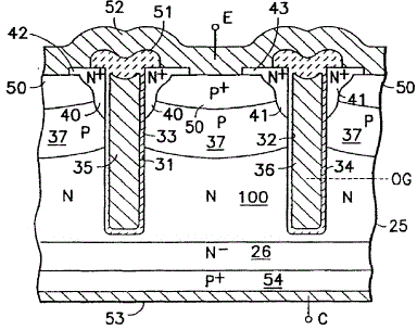
[0046] The sectional structu...


PUM


Abstract

The invention belongs to the technical field of insulated gate field effect transistors and particularly relates to a trench type insulated gate field effect transistor and a manufacture method thereof. According to the trench type insulated gate field effect transistor, a thick insulating medium layer is arranged at the bottom of a grid trench so as to increase breakdown voltage of the insulated gate field effect transistor and reduce stray capacitance of the insulated gate field effect transistor; meanwhile, a small groove is formed in the bottom of the grid trench, so that a field oxidation stress transition area is extended, the problem of current leakage caused by field oxidation stress is well solved, and reliability of devices is improved. According to the trench type insulated gate field effect transistor and the manufacture method thereof, by means of a self-alignment process, the groove in the bottom of the grid trench is formed, the process is simple, and the trench type insulated gate field effect transistor is easy to control.

Description

technical field [0001] The invention belongs to the technical field of insulated gate field effect transistor (IGBT), in particular to a trench type insulated gate field effect transistor and a manufacturing method thereof. [0002] Background technique [0003] The insulated gate field effect transistor (IGBT) is a device composed of a MOS transistor and a bipolar transistor. Its input is a MOS transistor and its output is a PNP (or NPN) transistor. It combines the advantages of these two devices. It not only has the advantages of low driving power and fast switching speed of MOS transistors, but also has the advantages of low saturation voltage and large capacity of bipolar devices. Its frequency characteristics are between MOS transistors and power transistors, and can work normally at a frequency of tens of kHz. Within the scope, it has been more and more widely used in modern power electronics technology, especially occupying a dominant position in the application of h...

Claims


Application Information

Patent Timeline
Patent Type & Authority Applications(China)
IPC IPC(8): H01L29/78H01L29/423H01L21/336
CPCH01L29/7397H01L29/4236H01L29/66348
Inventor 刘磊林曦王鹏飞龚轶
Owner SUZHOU ORIENTAL SEMICONDUCTOR CO LTD
Why Eureka
Try Eureka