Method for locating EMI (Electromagnetic Interference) noise of switch power supply rapidly

A technology for positioning switches and switching power supplies, applied in electrical components, output power conversion devices, etc., can solve problems such as strong harmonic interference and peak interference, communication system transmission data errors, electronic equipment dysfunction, etc., to achieve complete and accurate transmission. , to ensure the normal work, the effect of convenient operation

Active Publication Date: 2014-10-22
SHANDONG CHAOYUE DATA CONTROL ELECTRONICS CO LTD
View PDF12 Cites 1 Cited by
  • Summary
  • Abstract
  • Description
  • Claims
  • Application Information

AI Technical Summary

Problems solved by technology

However, due to the high operating frequency of the switching power supply, the internal current and voltage changes quickly, that is, dv/dt and di/dt, which will cause the switching power supply module to generate strong harmonic interference and spike interference, and through conduction, radiation and crosstalk S...

Method used


Image

  • Method for locating EMI (Electromagnetic Interference) noise of switch power supply rapidly

Examples


Embodiment 1

[0015] The method steps are as follows:

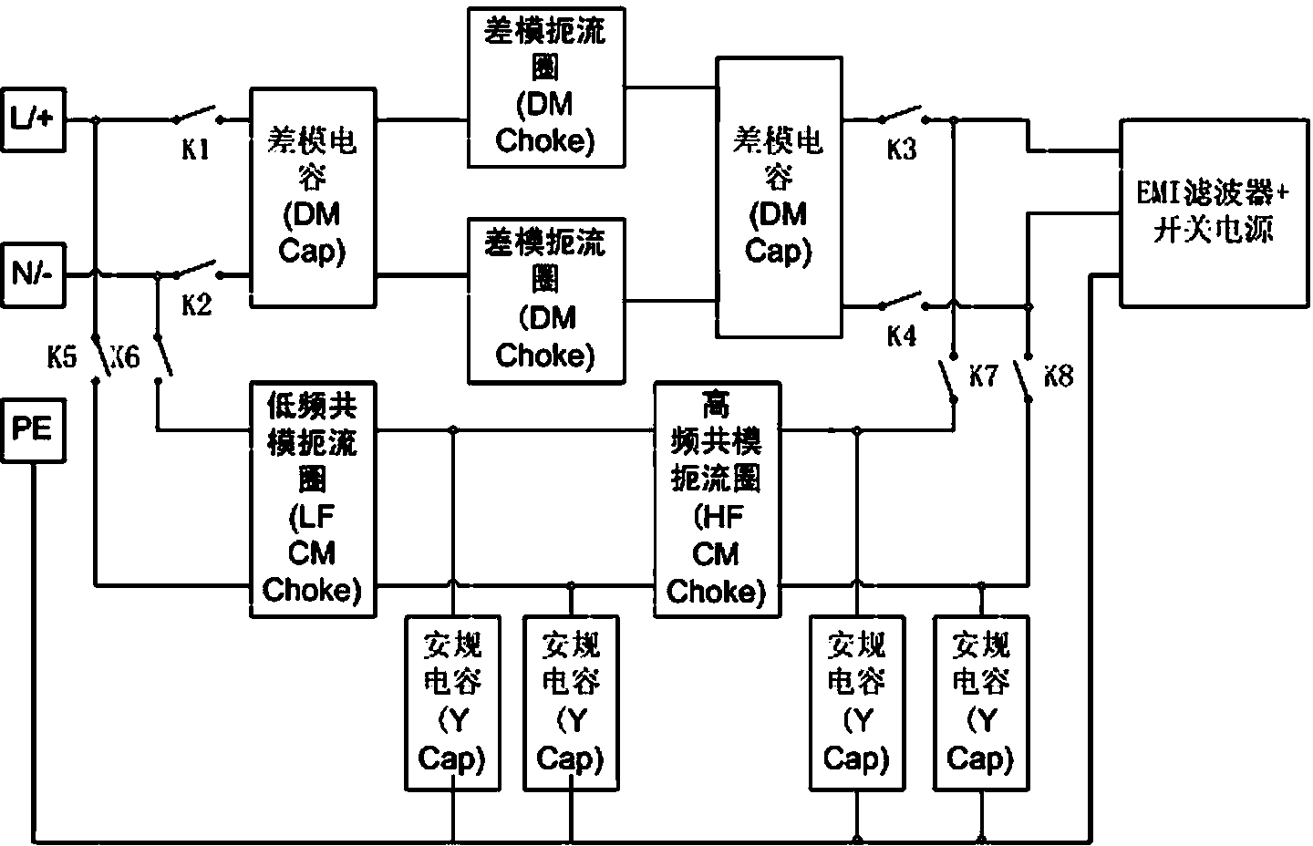
[0016] First conduct a conduction test on the switching power supply according to the standard EMI test method, and then locate the EMI noise at the frequency point exceeding the standard limit; use a differential mode capacitor and a differential mode choke to form a differential mode noise filter network, and use a common mode Mode choke coils form a common-mode noise filter network; the differential-mode filter network and the common-mode filter network are connected in parallel on the filter carrier board, and a switch is used to control the effectiveness of the differential-mode and common-mode filter networks, and the filter carrier board is connected in series to the input of the switching power supply At the end, verify whether the noise frequency band exceeding the standard is common-mode interference or differential-mode interference.

Embodiment 2

[0018] The method steps are as follows:

[0019] Set switches K1, K2, K3, K4, K5, K6, K7, and K8; switches K1, K2, K3, and K4 control the on-off of the differential-mode interference filter network; switches K5, K6, K7, and K8 control the common-mode interference filter network on and off. First close K1, K2, K3, and K4, and disconnect K5, K6, K7, and K8. At this time, the differential-mode filter network is valid, but the common-mode filter network is invalid. Then, power on and load the switching power supply to full load to verify the frequency point exceeded in the previous test. ;If the suppression effect on the over-standard frequency point is obvious in this mode, it can be judged that this frequency point is differential mode noise; if the suppression effect is not obvious or has no effect at all, close K5, K6, K7, and K8 to ensure that the switching power supply continues to work, and disconnect K1, K2, K3, K4, if the effect of suppressing the over-standard frequency...

Embodiment 3

[0021] The method steps are as follows:

[0022] Set switches K1, K2, K3, K4, K5, K6, K7, and K8; switches K1, K2, K3, and K4 control the on-off of the differential-mode interference filter network; switches K5, K6, K7, and K8 control the common-mode interference filter network on and off. The common mode choke coil is composed of a low frequency common mode choke coil and a high frequency common mode choke coil, wherein the low frequency common mode choke coil adopts a manganese zinc core, and the high frequency common mode choke coil adopts a nickel zinc core. First close K1, K2, K3, and K4, and disconnect K5, K6, K7, and K8. At this time, the differential-mode filter network is valid, but the common-mode filter network is invalid. Then, power on and load the switching power supply to full load to verify the frequency point exceeded in the previous test. ;If the suppression effect on the over-standard frequency point is obvious in this mode, it can be judged that this frequ...


PUM


Abstract

The invention discloses a method for locating EMI (electromagnetic Interference) noise of a switch power supply rapidly. The method comprises the following steps of: firstly, performing conduction test on the switch power supply according to a standard EMI testing method and then locating the EMI noise for a frequency point beyond a standard limiting value; establishing a differential mode noise filter network by using a differential mode capacitor and a differential mode choking coil, and establishing a common-mode noise filter network by using a common-mode capacitor and a common-mode choking coil; connecting the differential mode filter network and the common-mode filter network on a filtering carrier plate in parallel, controlling the effectiveness of the differential mode filter network and the common-mode filter network by using a switch, connecting the filtering carrier plate in series at the input end of the switch power supply, and verifying whether the noise frequency band beyond the standard is common-mode interference or differential-mode interference. Compared with the prior art, the method for locating the EMI noise of the switch power supply rapidly has the characteristics of being rational in design, convenient to operate and the like, efficiently guarantees normal work of electronic devices around, enables a communication system to transmit data completely and exactly, and reduces occurrence of abnormal conditions of the system such as halt and alarm.

Description

[0001] technical field [0002] The invention relates to the technical field of power supply noise processing, in particular to a method for quickly locating the EMI noise of a switching power supply. Background technique [0003] EMI (Electromagnetic Interference) Chinese translation: electromagnetic interference. It refers to the interference phenomenon caused by the interaction between electromagnetic waves and electronic components. There are two types of conduction interference and radiation interference. Conducted interference refers to the coupling (interference) of a signal on one electrical network to another electrical network through a conductive medium. Radiation interference means that the interference source couples (interferences) its signal to another electrical network through space. In high-speed PCB and system design, high-frequency signal lines, integrated circuit pins, and various connectors may all become antennas. It is a characteristic radiation int...

Claims


Application Information

Patent Timeline
IPC IPC(8): H02M1/44
Inventor 徐成焱耿士华
Owner SHANDONG CHAOYUE DATA CONTROL ELECTRONICS CO LTD
Why Eureka
Try Eureka