
Correcting method, correcting device and measuring apparatus for laser ranging

A technology of laser distance measurement and calibration method, applied in the direction of instruments, radio wave measurement systems, etc., can solve the problems of long circuit response time, easy mechanical failure, short service life, etc., to eliminate temperature drift, strengthen application, and reduce costs Effect

Inactive Publication Date: 2014-10-29
杜学璋
View PDF4 Cites 12 Cited by
  • Summary
  • Abstract
  • Description
  • Claims
  • Application Information

AI Technical Summary

Problems solved by technology

[0016] In order to solve the above-mentioned technical problems, the object of the present invention is to provide a laser ranging calibration that solves the problems of long circuit response time, easy mechanical failure, short service life or high cost, and easy generation of co-frequency interference in the prior art. Method, calibration device and measuring instrument

Method used


Image

  • Correcting method, correcting device and measuring apparatus for laser ranging
  • Correcting method, correcting device and measuring apparatus for laser ranging
  • Correcting method, correcting device and measuring apparatus for laser ranging

Examples


Embodiment 1

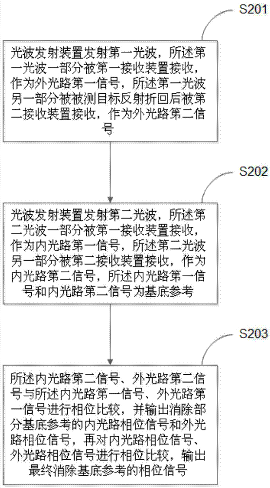
[0058] The invention provides a calibration method for laser distance measurement, adopting two receiving systems to successively receive two kinds of light waves emitted by the transmitting device, through calibration, the temperature drift caused by ambient temperature and self-heating can be eliminated; at the same time, optical transmitting systems with different wavelengths and The optical filter group effectively separates the internal and external optical paths. Compared with the traditional dual-transmission and dual-reception scheme, the laser tubes of the same wavelength are placed at different positions or angles in the structure, which improves the compactness of the system and reduces the radio frequency crosstalk and interference caused by scattered emission.

[0059] The implementation process of the laser ranging calibration method provided in this embodiment is as follows: figure 1 As shown, the details are as follows:

[0060] Step S 201 , the transmitting d...

Embodiment 2

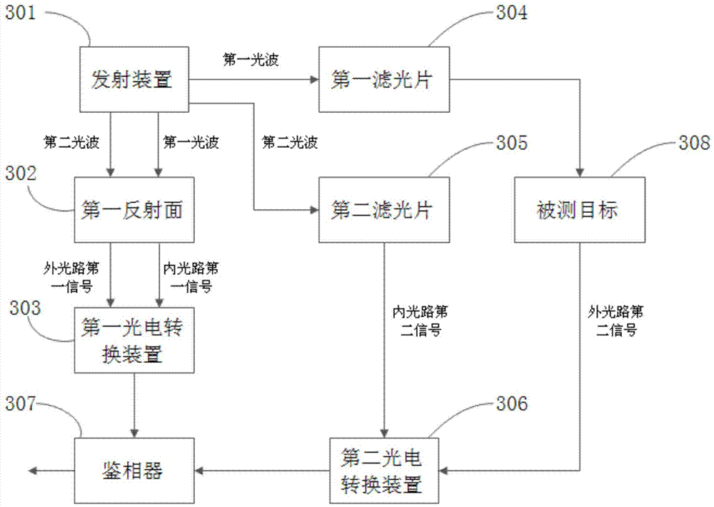
[0091] This embodiment provides a calibration device for laser ranging. The calibration device for laser ranging is based on the laser ranging calibration method of double-transmission, double-receiver, and dual-optical-path phase measurement, and adopts a dual-channel integrated transmitter. Its structural principle is as follows: image 3 As shown, for the convenience of description, this embodiment only provides the part related to the embodiment of the present invention.

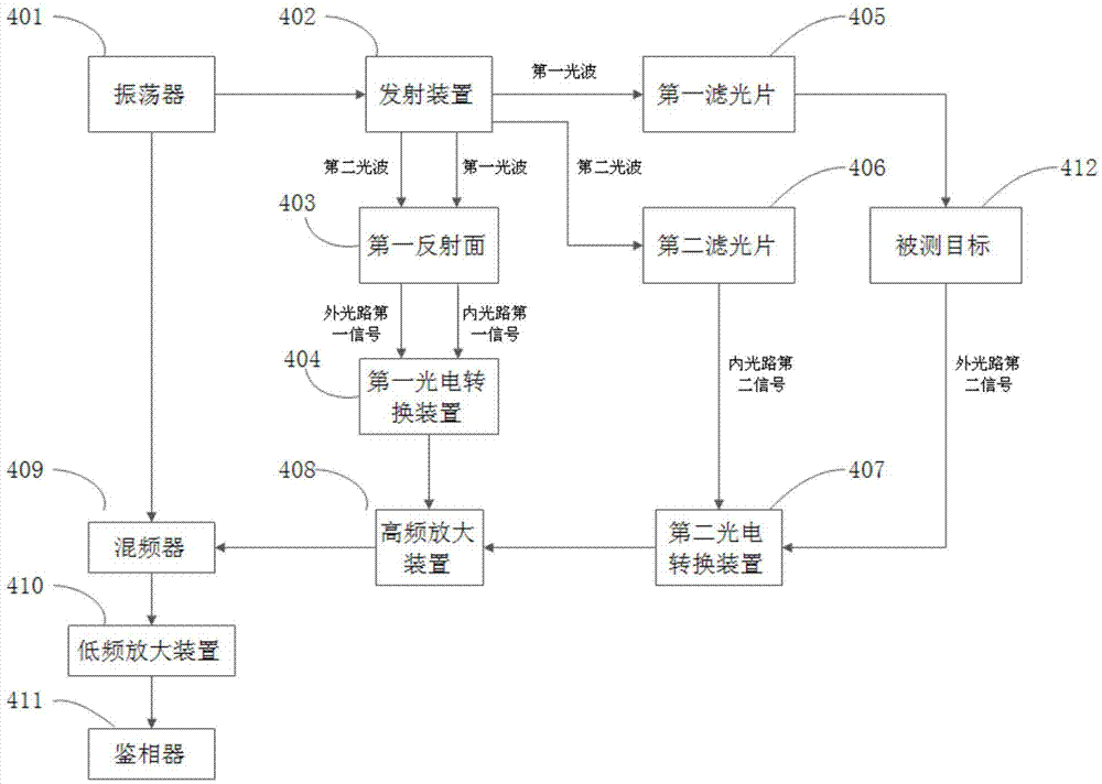
[0092] A laser ranging calibration device provided in this embodiment includes an oscillator 401, a transmitting device 402, a first reflecting surface 403, a first photoelectric conversion device 404, a first optical filter 405, a second optical filter 406, The second photoelectric conversion device 407 , and the high frequency amplification device 408 , the mixer 409 , the low frequency amplification device 410 and the phase detector 411 .

[0093] Compared with the first embodiment, this embodiment di...

Embodiment 3

[0101] This embodiment provides a calibration device for laser ranging. The calibration device for laser ranging is based on the laser ranging calibration method of double-transmission, double-receiver, and dual-optical-path phase measurement, and adopts a dual-channel integrated transmitter. Its structural principle is as follows: Figure 4 As shown, for the convenience of description, this embodiment only provides the part related to the embodiment of the present invention.

[0102] Compared with Embodiment 2, this embodiment differs in that the first photoelectric conversion device 404 and the second photoelectric conversion device 407 are replaced by two receiving devices together with the mixer 409, and the receiving devices simultaneously implement the photoelectric conversion device 404 , 407 and mixer 409, the receiving device can be one or more photodiodes, phototransistors, APDs, PMTs (photomultiplier tubes) and other devices with photoelectric conversion functions. ...


PUM


Abstract

The invention relates to a correcting method, a correcting device and a measuring apparatus for laser ranging. The correcting method for the laser ranging solves the problems of long circuit response time, easiness in mechanical fault generation, short service life or high cost and easiness in same frequency interference generation of the prior art. The correcting method includes steps of enabling an emitting device to emit a first light wave, wherein one part of the first light wave is received by a first receiving device and serves as the first signal of an external light path, and the other part of the first light wave is received by a second receiving device and serves as the second signal of the external light path after being reflected by a measured object; enabling an emitting device to emit second light wave of different wavelengths, wherein one part of the second light wave is received by the first receiving device and serves as the first signal of an internal light path, and the other part of the second light wave is received by the second receiving device and serves as the second signal of the internal light path; comparing phases of the four paths of signals, outputting internal light path phase signals and external light path phase signals which only have part of basal reference, and comparing the phases of the internal light path phase signals and external light path phase signals to output phase signals without basal reference.

Description

technical field [0001] The invention belongs to the field of photoelectric ranging, and in particular relates to a calibration method, a calibration device and a measuring instrument for laser ranging. Background technique [0002] Laser ranging, because of its high measurement accuracy up to millimeter level, is widely used in short-distance laser ranging within 200 meters. The laser ranging based on the principle of phase difference measurement is to irradiate the measured target with a modulated laser beam. The laser beam is reflected by the measured target and then turned back. The phase change generated during the round-trip process of the laser beam is converted into the distance of the measured target. The accuracy and precision of the distance measuring device are affected by the characteristics of the internal parts of the distance measuring device. The higher the precision requirement of the laser ranging instrument, the complexity of its circuit and the demand fo...

Claims


Application Information

Patent Timeline
Patent Type & Authority Applications(China)
IPC IPC(8): G01S7/497
CPCG01S7/497
Inventor 杜学璋
Owner 杜学璋
Learn More