Vacuum optical coating machine capable of moving along with workpiece and in-place dynamically monitoring membrane thickness

An optical coating machine, dynamic monitoring technology, applied in vacuum evaporation coating, sputtering coating, ion implantation coating and other directions, can solve the problems of easy failure, low reliability, affecting film thickness accuracy and repeatability, etc. To achieve the effect of simplifying the complex structure, reducing the failure rate and improving reliability

Active Publication Date: 2014-11-05
DONGGUAN HUICHENG VACUUM TECH
View PDF7 Cites 12 Cited by
  • Summary
  • Abstract
  • Description
  • Claims
  • Application Information

AI Technical Summary

Problems solved by technology

[0009] This in-situ dynamic thickness measurement method has made significant progress, but there are still the following unsatisfactory points: (1) The main unit of the thickness gauge and the probe electric wire and The lead-out of the signal line, the entry and exit of the cooling water circuit of the probe, the drive connection of the workpiece turret in the furnace, the transmission mechanism of the power outside the furnace, and the vacuum dynamic seal are all concentrated on the structure where the rotating shaft is located at the top section of the furnace, resulting in congestion of the upper structure of the rotating shaft. Complex, low reliability, and prone to failure; (2) The workpiece turret has poor motion stability and large vibration, which affects the accuracy and repeatability of film thickness measurement; (3) The host of the thickness gauge needs to replace the power supply battery regularly

Method used


Image

  • Vacuum optical coating machine capable of moving along with workpiece and in-place dynamically monitoring membrane thickness
  • Vacuum optical coating machine capable of moving along with workpiece and in-place dynamically monitoring membrane thickness
  • Vacuum optical coating machine capable of moving along with workpiece and in-place dynamically monitoring membrane thickness

Examples


Embodiment Construction

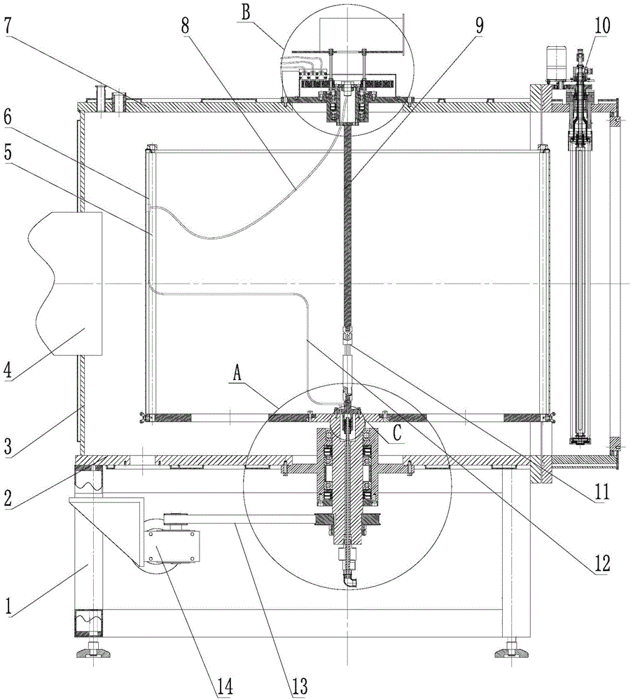
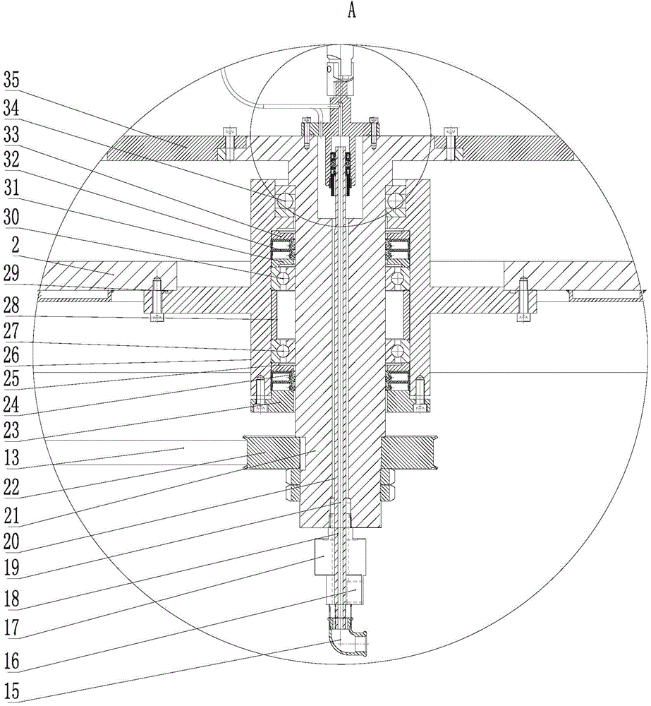
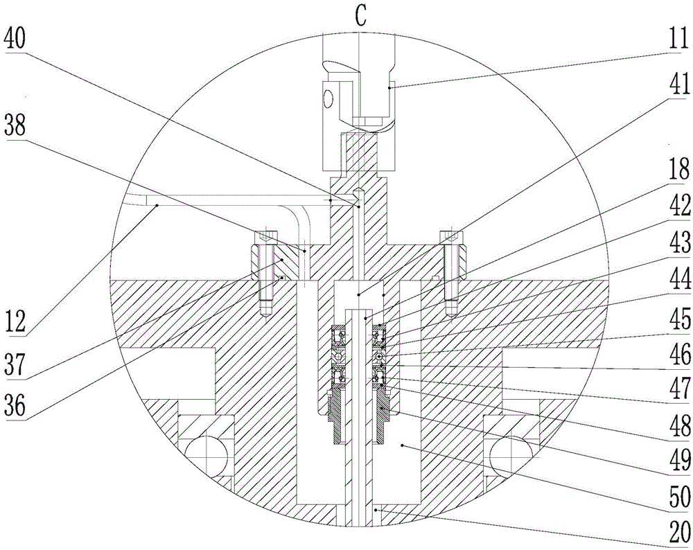
[0033] figure 1 A schematic diagram of the main structure of the vacuum optical coating machine of this embodiment. Such as figure 1 As shown, the vacuum optical coating machine includes a furnace body, a rotating shaft, a workpiece turret 5 , a rotating shaft driving mechanism, a crystal oscillator probe 6 and a film thickness controller host 73 . The furnace body is composed of a furnace wall 3, a furnace body chassis 2 and a furnace body top plate 7. The lower part of the furnace body is supported by a furnace body support 1. The furnace wall 3 is provided with an air extraction port 4 connected with a vacuum unit, so that the furnace body can be removed during coating. Vacuum it. The rotating shaft is vertically installed in the middle of the furnace body, and consists of the lower transmission shaft 21, the upper transmission connector 37, the universal coupling 11, the upper extension shaft 9 and the upper transmission shaft 52, which are connected sequentially from bo...


PUM


Abstract

The invention discloses a vacuum optical coating machine capable of moving along with workpiece and in-place dynamically monitoring the membrane thickness. The host of a membrane thickness controller is arranged on the upper end of a rotation shaft above the top plate of a furnace body, a crystal oscillation probe is arranged on a workpiece rotation rack, the conductive wire and signal wire of the crystal oscillation probe hermetically go through the furnace body from a hollow cavity in the upper part of the rotation shaft; a cooling water circuit hermetically goes through the furnace body from a hollow cavity in the lower part of the rotation shaft, and the separated delivery is achieved in the crystal oscillation probe. The cooling water circuit and the conductive wire and signal wire of a crystal oscillation probe are respectively transferred from the lower part and the upper part of a transmission shaft of a furnace body, the conventional transfer mode that the cooling water circuit, the conductive wire, and the signal wire are all transferred in the upper part of a transmission shaft, is changed, the water transfer and electric transfer are separated, the complicated structure of the transmission shaft is simplified, the reliability of equipment is improved, and the fault rate is reduced.

Description

technical field [0001] The invention relates to a vacuum optical coating machine for on-site dynamic monitoring of film thickness, in particular to a fully automatic optical coating machine with an on-site real-time monitoring device for film thickness moving with workpieces. Background technique [0002] The coating process of the optical coating machine mostly uses a quartz crystal film thickness meter (film thickness meter for short) to monitor the film thickness change. The most traditional method is that the coating material in the crucible is heated and evaporated from the bottom to the top, and deposited on the workpiece above. The quartz crystal probe (referred to as the probe) of the film thickness meter is generally installed at a fixed position in the center of the furnace roof that does not move with the workpiece, and the film thickness signal is sent to the film thickness meter host outside the furnace through the transmission wire. [0003] This most traditio...

Claims


Application Information

Patent Timeline
Patent Type & Authority Applications(China)
IPC IPC(8): C23C14/54
Inventor 李志荣李志方罗志明陸创程
Owner DONGGUAN HUICHENG VACUUM TECH
Why Eureka
Try Eureka