Automatic test method for directional diagram of short-wave large-scale antenna array

An automatic test and antenna array technology, applied in the field of communication, can solve the problems that affect the stability of the airship's attitude, take off and land, the technical level has not reached the comprehensive test, and the technical means are single, so as to facilitate real-time data processing, realize feasibility and reliability Operability and error reduction effect

Inactive Publication Date: 2014-11-05
THE 22ND RES INST OF CHINA ELECTRONICS TECH GROUP CORP
View PDF5 Cites 23 Cited by
  • Summary
  • Abstract
  • Description
  • Claims
  • Application Information

AI Technical Summary

Problems solved by technology

Manned airships and airplanes are tested by a pilot driving a powered flying object, and the flight path can be controlled artificially. However, the biggest disadvantage of this type of test method is that when testing the transmitting antenna array, the electromagnetic waves generated by the transmitting array are easy to cause damage to the carrier. The power system of the airship and aircraft interferes, which affects the stability of the airship's attitude, take-off and landing, or even flameout, which poses a certain safety hazard
[0008] The technical level of the directional test of the domestic large-scale shortwave antenna array has not yet met the requirements of all-round testing, and the technical means are single and subject to various conditions.

Method used

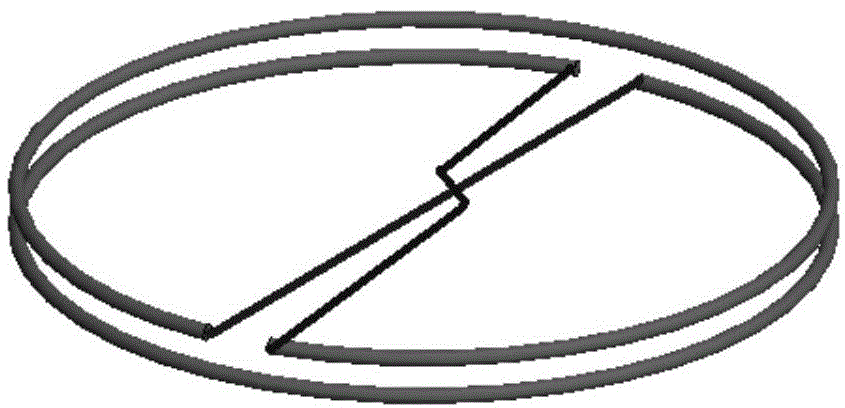
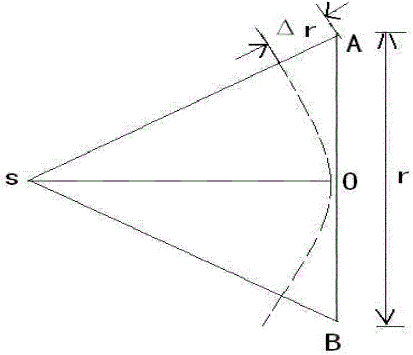
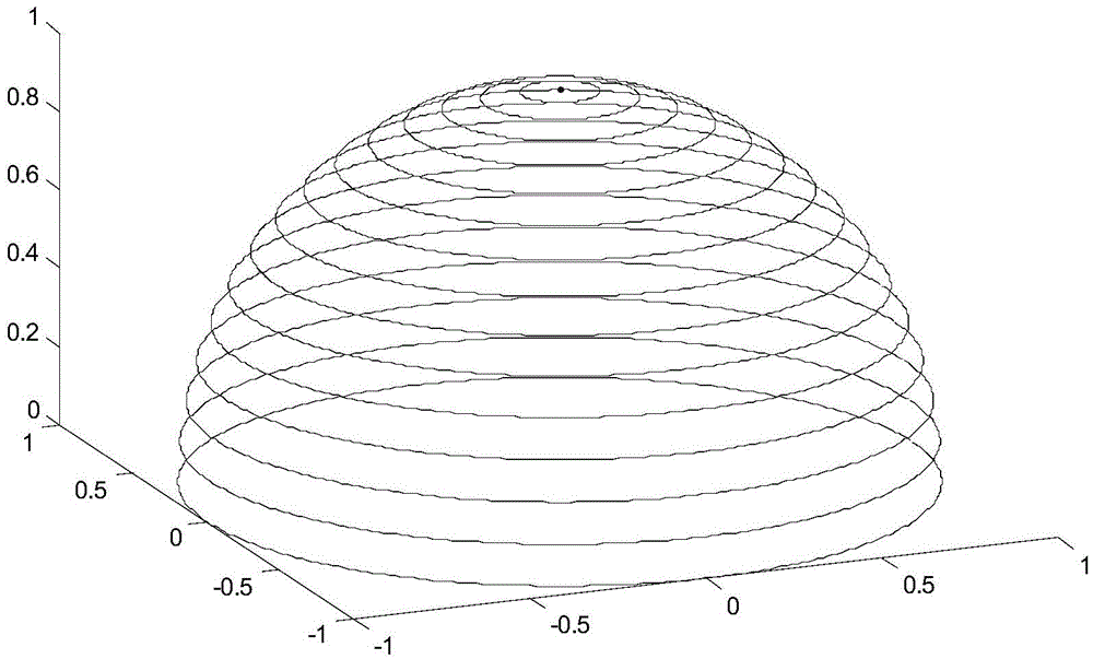

Image

  • Automatic test method for directional diagram of short-wave large-scale antenna array
  • Automatic test method for directional diagram of short-wave large-scale antenna array
  • Automatic test method for directional diagram of short-wave large-scale antenna array

Examples


Embodiment 1

[0022] Embodiment 1, this embodiment discloses a method for automatically testing the pattern of a short-wave scale antenna array, including the following steps:

[0023] Step A: Composition of the antenna test system;

[0024] Step B: fully automatic real-time testing system;

[0025] Step C: data processing and fitting method;

[0026] Wherein, the step A specifically includes:

[0027] Step A1: Design of auxiliary antenna;

[0028] Step A2: receiving antenna and spatial positioning device;

[0029] Wherein, the step B specifically includes:

[0030] Step B1: Antenna test automatic recording system;

[0031] Step B2: real-time communication system;

[0032] Wherein, the step C specifically includes:

[0033] Step C1: array pattern fitting;

[0034] Step C2: Test data judgment and error handling methods.

[0035] Specifically, the technical solution of this embodiment is: a real-time automatic testing method for unmanned aerial vehicles. The method covers the follow...


PUM


Abstract

The invention discloses an automatic test method for a directional diagram of a short-wave large-scale antenna array. The method includes the following steps: (1) 2D<2> / Lambda is used as a minimum test distance, wherein R is a distance between a to-be-tested antenna and a signal source, D is a maximum aperture of the antenna array and Lambda is a work wavelength; a test track is concentric circles which rise gradually with radiuses being reduced gradually; (2) test field intensity data and space GPS orientation data are combined and interferences and noise signals are removed and then through an algorithm, an overall directional diagram is calculated in an inversion manner. In the automatic test method, the whole system adopts a radio communication means to carry out whole-journey remote control on a test process so that test efficiency is improved and a function which cannot be achieved by the prior manual tests is realized; and at the same time, intervention of an automation device reduces errors caused by the manual tests and the accuracy and precision are improved.

Description

technical field [0001] The invention relates to an automatic test method for the pattern of a short-wave scale antenna array in the communication field. Background technique [0002] The antenna pattern parameter is one of the important index parameters of the antenna. It gives the change of radiation with angle at a fixed distance from the antenna when the antenna is transmitting, and represents the peak ratio of the radiation power density of an antenna to the average distribution of the radiation power around the antenna. When the power density is much larger. The pattern reflects the characteristics of the antenna radiation field, and the measurement of the antenna pattern can accurately grasp the spatial radiation characteristics of the actual antenna. [0003] Compared with our common antenna system arrays, shortwave antenna arrays are larger in size and scale. The common 3-30MHz short-wave antenna array has a diameter of more than 100 to 200 meters, and the space po...

Claims


Application Information

Patent Timeline
Patent Type & Authority Applications(China)
IPC IPC(8): G01R29/10
Inventor 朱文军何绍林朱金鹏邓冀云
Owner THE 22ND RES INST OF CHINA ELECTRONICS TECH GROUP CORP
Why Eureka
Try Eureka