
Chemical waste gas treatment device and treatment technology

A waste gas treatment device and chemical technology, applied in the direction of incinerators, chemical instruments and methods, combustion methods, etc., can solve the problems of hidden safety hazards in chemical production areas, difficult disassembly and replacement of devices, and high safety requirements, so as to improve the effect of waste gas treatment, Prevents backburning flames and improves treatment effects

Active Publication Date: 2014-11-12
ZHEJIANG UNIV +1
View PDF5 Cites 6 Cited by
  • Summary
  • Abstract
  • Description
  • Claims
  • Application Information

AI Technical Summary

Problems solved by technology

The device has the advantages of wide application range of organic waste gas concentration, low input energy, high treatment effect, and high system controllability. However, the invention combines porous media materials with plasma, which makes the device difficult to disassemble and replace, and the device can only be degraded. Organic matter in exhaust gas, poor effect on inorganic matter in exhaust gas
[0007] In addition, due to the high safety requirements in chemical production areas, ignition sources are usually strictly prohibited. However, there are combustion reactors in chemical waste gas treatment devices, which often cause deflagration and affect chemical production areas. Therefore, there are likely to be safety hazards in chemical production areas.

Method used


Image

  • Chemical waste gas treatment device and treatment technology
  • Chemical waste gas treatment device and treatment technology

Examples


Embodiment 1

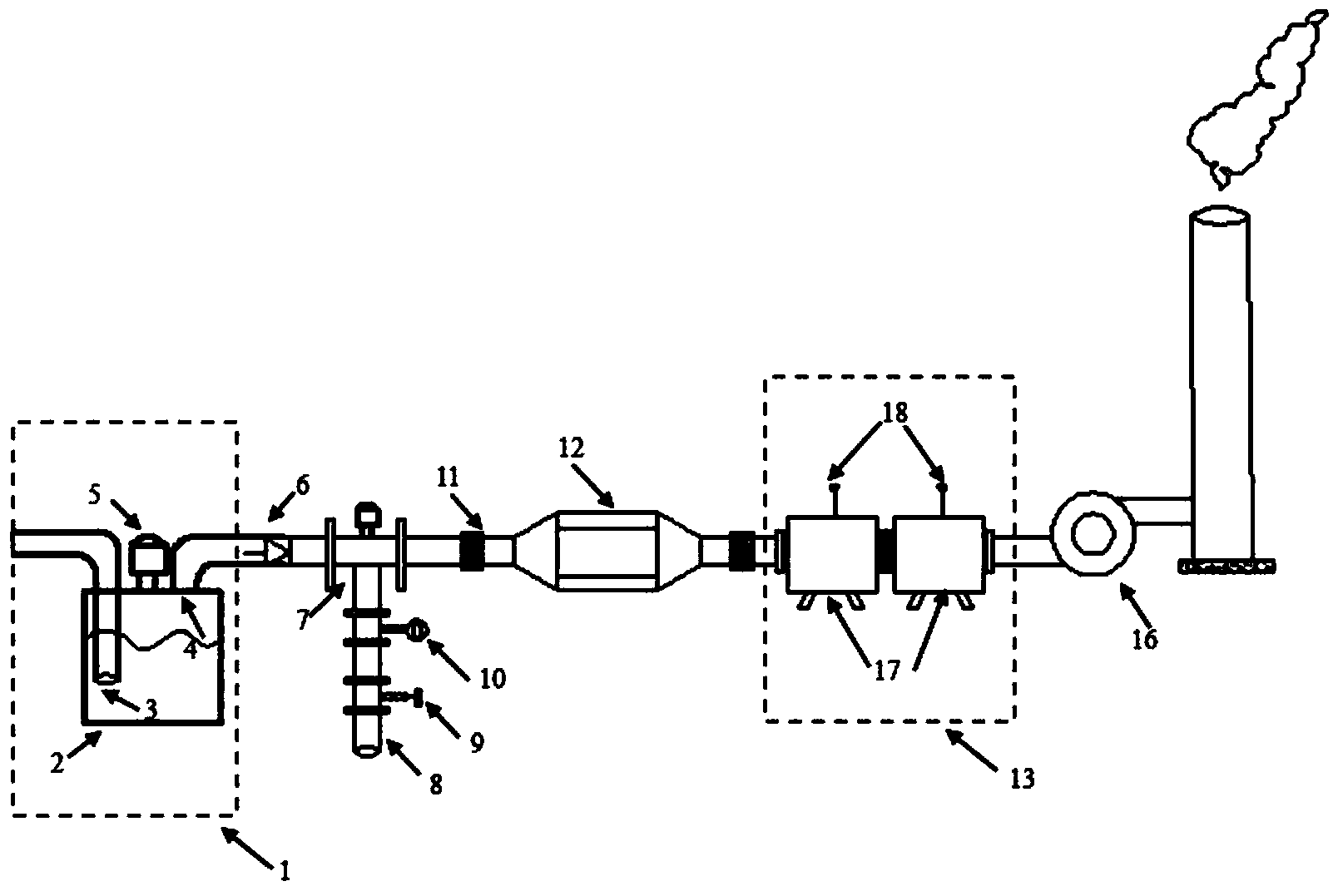
[0034] Such as figure 1As shown, a chemical waste gas treatment device includes an explosion-proof container 1 , a gas mixer 7 , a plasma reactor 12 and a catalytic combustion reactor 13 connected in sequence. The explosion-proof container 1 comprises a water-holding container 2, an air inlet pipe 3 extending into the liquid surface of the container and an air outlet pipe 4 arranged at the top of the container. The distance between the mouth of the air inlet pipe 3 and the water surface must not be less than 100 mm, and the height of the mouth of the air outlet pipe 4 above the water surface must be greater than 50 mm. The air inlet pipe 3 of the explosion-proof container 1 extends into the water surface of the container to dissolve part of the water-soluble organic pollutants in the waste gas into the water. The explosion-proof container 1 is placed at the forefront of the whole device, that is, the upstream of the gas mixer 7, which can isolate the fire source and ensure th...


PUM


Abstract

The invention discloses a chemical waste gas treatment device. The device comprises an anti-explosion container, a gas mixer, a plasma reactor and a catalytic combustion reactor which are all connected in sequence. The anti-explosion container comprises a water containing body, a gas inlet pipe stretching into liquid of the containing body and a gas outlet pipe arranged on the top of the containing body. The catalytic combustion reactor is composed of a front segment filled with the CO catalyst and a rear segment filled with a porous medium. The invention further discloses a technology for treating chemical waste gas through the device. The mode that the plasma reactor and the catalytic combustion reactor are combined is adopted for the device, so that the waste gas treatment effect of the whole device is improved; the anti-explosion container is further arranged on the upstream of the gas mixer, air is prevented from flowing back, backdraft flames generated in reaction in the plasma reactor or the catalytic combustion reactor are prevented, and the safety of the device is improved; water-soluble organic pollutants in waste gas are dissolved in water in the anti-explosion container, and thus the waste gas treatment effect of the device can be improved easily.

Description

technical field [0001] The invention relates to the field of purification and removal of chemical waste gas, in particular to a chemical waste gas treatment device and a process for treating chemical waste gas by using the device. Background technique [0002] The chemical industry is an important pillar industry of my country's national economy. However, the waste gas produced in chemical production often contains a variety of pollutants. These pollutants usually have complex physical and chemical properties, which are easy to cause great pollution to the environment and also affect human health. . To this end, my country has introduced strict regulations and norms to control the emission of chemical waste gas. For example, GB16297-1996 "Comprehensive Emission Standard of Air Pollutants", which limits the emission value of 33 kinds of emissions. [0003] In the prior art, there are many methods for treating chemical waste gas, generally including adsorption method, catalyt...

Claims


Application Information

Patent Timeline
IPC IPC(8): B01D53/32B01D47/02F23G7/07
Inventor 周昊时伟岑可法
Owner ZHEJIANG UNIV
Learn More