
Paint-spraying waste gas integrated treatment method

A treatment method and exhaust gas technology, applied in the direction of chemical instruments and methods, separation methods, combined devices, etc., can solve the problems of long process flow, environmental air pollution, complex equipment, etc., and achieve good treatment effect, high treatment efficiency and simple structure Effect

Inactive Publication Date: 2014-11-19
ZUNYI TIANLI ENVIRONMENTAL ENG
View PDF2 Cites 4 Cited by
  • Summary
  • Abstract
  • Description
  • Claims
  • Application Information

AI Technical Summary

Problems solved by technology

[0002] In the prior art, the painting process is widely used in industries such as machinery, electrical equipment, home appliances, automobiles, ships, and furniture. The spraying agent used for painting is mainly paint, and a certain amount of exhaust gas is discharged during the production process. The components are organic pollutants such as paint dust (paint mist) and volatilized benzene and benzene series (VOC for short), which cause ambient air pollution and must be treated to meet environmental protection emission requirements. Therefore, the exhaust gas treatment of the spray booth is a part of the spray production process. The existing paint waste gas treatment methods mainly include isolation method, combustion method, absorption method, condensation method, plasma low-temperature catalytic oxidation method, adsorption method, etc., these methods have their own advantages and disadvantages, most of the existing enterprises use a single The treatment method cannot realize the simultaneous treatment of liquid paint mist and insoluble water VOC in the exhaust gas. Although some have realized the combination of various methods, there are long process flow, complicated equipment, large area of ​​the entire treatment system, and poor control. Convenience, poor processing effect and other disadvantages

Method used


Image

  • Paint-spraying waste gas integrated treatment method
  • Paint-spraying waste gas integrated treatment method

Examples


Embodiment Construction

[0014] The present invention will be described in further detail below in conjunction with accompanying drawing, but should not be interpreted as that the scope of the subject matter of the present invention is limited to following embodiment, under the situation of not departing from above-mentioned technical idea of ​​the present invention, all according to the common technical knowledge of this field and Various modifications, substitutions and alterations made by conventional means are included within the scope of the present invention.

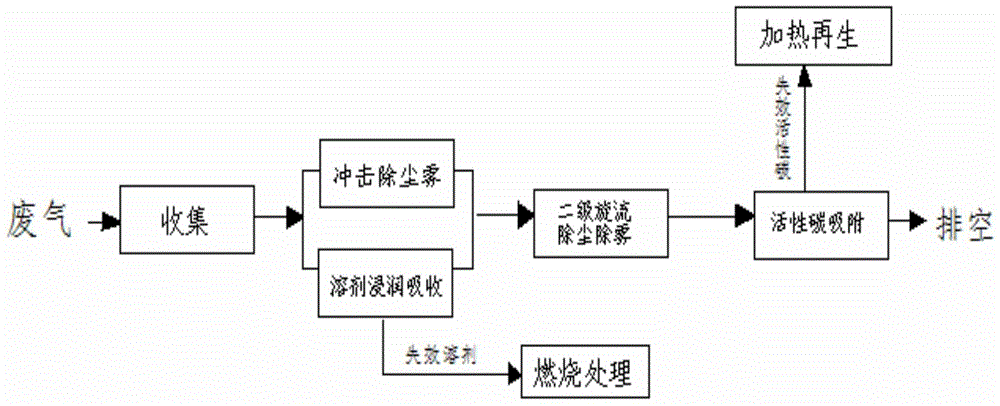
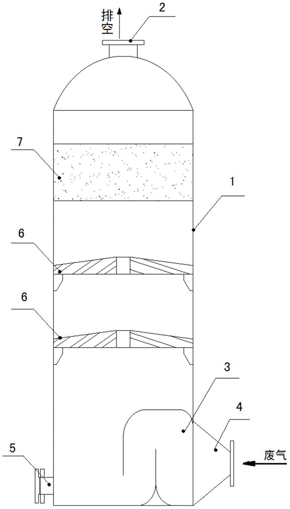
[0015] like figure 1 , 2 As shown, an integrated treatment method for spray paint exhaust gas, the exhaust gas containing paint mist and VOC generated in the painting process is collected through the collection cover, and then transported to the processing device by the conveying pipeline under the negative pressure of the induced draft fan. The processing device mainly It consists of a shell 1 and an impact defogging device 3, a gas swi...


PUM


Abstract

The invention discloses a paint-spraying waste gas integrated treatment method. Waste gas produced in a paint-spraying process and containing paint mists and VOC is collected by a collecting hood, then is conveyed to a treatment device by a conveying pipeline and under the negative pressure action of a draught fan, and is up to standard for discharging after successively undergoing impact type dust-mist removal, solvent infiltration absorption, two-stage cyclone dust-mist removal and activated carbon adsorption treatment from bottom to top. The method organically combines various treatment technologies, not only achieves the integrated treatment of the paint mists and the VOC, but also has the advantages of simple and compact process equipment and structure and good treatment effect; and the waste gas after treatment can reach the ''integrated emission standard of air pollutants'' (GB16297-1996) second-grade emission standards, and the treatment efficiency of the VOC in the waste gas is high and can reach 99% or more.

Description

technical field [0001] The invention belongs to the technical field of spray paint waste gas treatment, in particular to an integrated treatment method for paint spray waste gas. Background technique [0002] In the prior art, the painting process is widely used in industries such as machinery, electrical equipment, home appliances, automobiles, ships, and furniture. The spraying agent used for painting is mainly paint, and a certain amount of exhaust gas is discharged during the production process. The components are organic pollutants such as paint dust (paint mist) and volatilized benzene and benzene series (VOC for short), which cause ambient air pollution and must be treated to meet environmental protection emission requirements. Therefore, the exhaust gas treatment of the spray booth is a part of the spray production process. The existing paint waste gas treatment methods mainly include isolation method, combustion method, absorption method, condensation method, plasma...

Claims


Application Information

Patent Timeline
IPC IPC(8): B01D50/00B01D53/00B01D53/14B01D53/04
Inventor 刘仁龙易德君唐小林
Owner ZUNYI TIANLI ENVIRONMENTAL ENG
Learn More