Microfluidic device for fluid detection and method for making the same

A technology for microfluidic devices and fluid detection, which is used in laboratory containers, chemical instruments and methods, processes for producing decorative surface effects, etc. It is difficult to process small-sized microstructures and other problems to achieve the effect of improving efficiency and enhancing etching rate

Active Publication Date: 2014-11-26
CHANGWEI SYST TECH (SHANGHAI) CO LTD
View PDF8 Cites 3 Cited by
  • Summary
  • Abstract
  • Description
  • Claims
  • Application Information

AI Technical Summary

Problems solved by technology

[0002] At present, most microfluidic devices are made of quartz, glass or high molecular polymer, the basic structure is shown in the figure, in which 1 is the main channel for the fluid to flow through on the device, and 2 and 3 are the outlets of the main channel (inlet) or inlet (outlet), in this type of device, the fluid can only flow along the plane of the device, and cannot flow in a direction perpendicular to the plane of the device
[0003] At the same time, CN101708439 and CN 101256145 also disclose a device structure with vertical channels, but none of these vertical channels can achieve the effect of penetrating the entire device
The reason for this problem is that in the traditional device preparation process, the glass or quartz material has high hardness, high melting point and relatively high price, especially, due to the traditional etching method, that is, a single dry etching or wet etching method is used. Etching or using one of

Method used


Image

  • Microfluidic device for fluid detection and method for making the same
  • Microfluidic device for fluid detection and method for making the same
  • Microfluidic device for fluid detection and method for making the same

Examples


Embodiment Construction

[0029] The advantages of the present invention will be further elaborated below in conjunction with the accompanying drawings and specific embodiments.

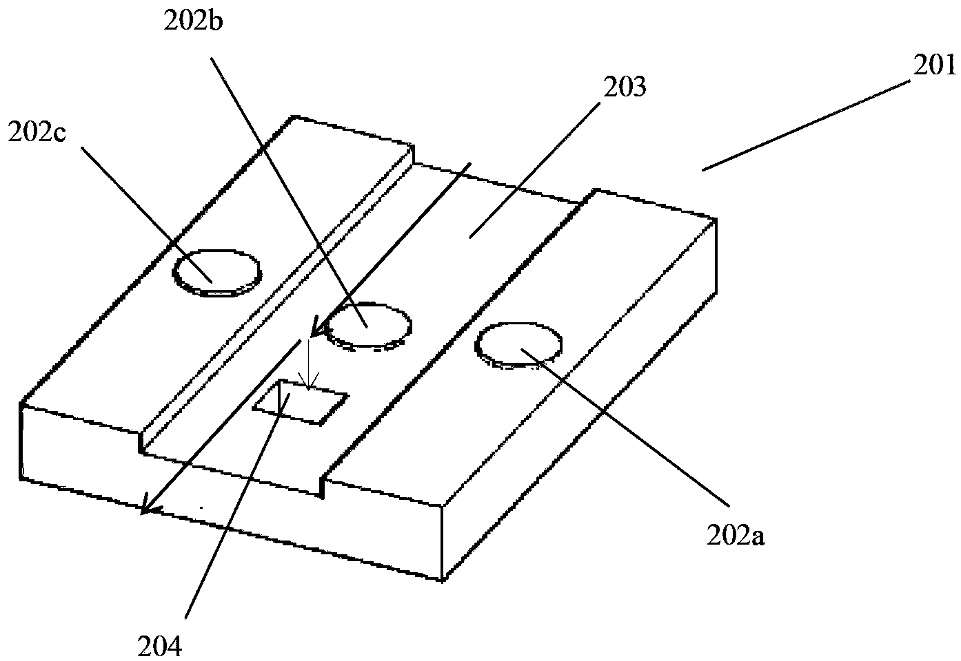
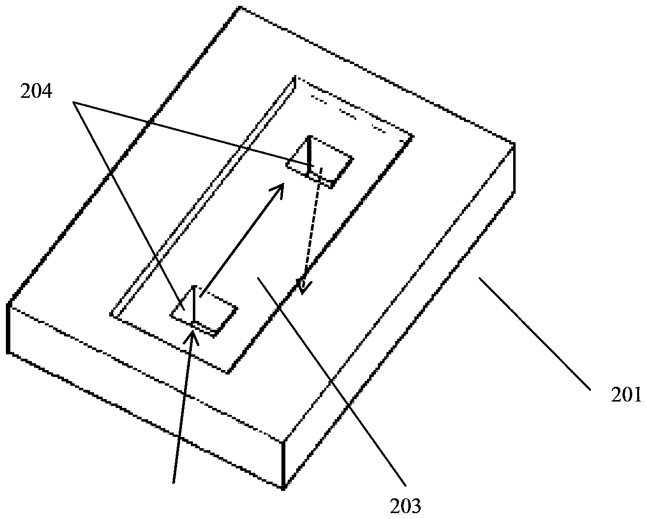
[0030] refer to Figure 2a and image 3 , is a structural schematic diagram of a preferred embodiment of the device structure of the present invention, the device 201 includes a substrate 208 and a third precipitation material 206 and a fourth precipitation material 207 deposited on the substrate sequentially from top to bottom, and the microfluidic The device is provided with three detection units 202a, 202b, 202c. One side of the microfluidic device has a groove 203. The groove 203 is a through-groove structure, which runs through the upper and lower ends of the device 201, and is provided in the groove. A microfluidic channel 204 runs through the microfluidic device. Among them, the fluid flow mode is as follows Figure 2a In the direction indicated by the middle arrow, the fluid flows into the groove 203 , and when pas...


PUM


Abstract

The invention discloses a microfluidic device for fluid detection. The microfluidic device includes a substrate, and a third precipitation material and a fourth precipitation material that are deposited on the substrate in order. Also, the microfluidic device is provided with one or more detection units. One side of the microfluidic device has one or more grooves, in which one or more microflow channels running through the microfluidic device are disposed.

Description

technical field [0001] The invention relates to a microfluidic device for fluid detection and a method for preparing the microfluidic device. Background technique [0002] At present, most microfluidic devices are made of quartz, glass or high molecular polymer, the basic structure is shown in the figure, in which 1 is the main channel for the fluid to flow through on the device, and 2 and 3 are the outlets of the main channel (inlet) or inlet (outlet), in this type of device, the fluid can only flow along the plane of the device, and cannot flow in a direction perpendicular to the plane of the device. [0003] At the same time, CN101708439 and CN101256145 also disclose a device structure with vertical channels, but none of these vertical channels can achieve the effect of penetrating the entire device. The reason for this problem is that in the traditional device preparation process, the glass or quartz material has high hardness, high melting point and relatively high pri...

Claims


Application Information

Patent Timeline
IPC IPC(8): B01L3/00B81C1/00
Inventor 杜学东娄达
Owner CHANGWEI SYST TECH (SHANGHAI) CO LTD
Why Eureka
Try Eureka