Chemical shift imaging method and system
A technology of chemical shift and imaging method, applied in the direction of using nuclear magnetic resonance imaging system for measurement, magnetic resonance measurement, measurement device, etc., can solve the problem of long imaging time, etc., and achieve the effect of shortening the acquisition time
- Summary
- Abstract
- Description
- Claims
- Application Information
AI Technical Summary
Problems solved by technology
Method used
Image
Examples
Embodiment 1
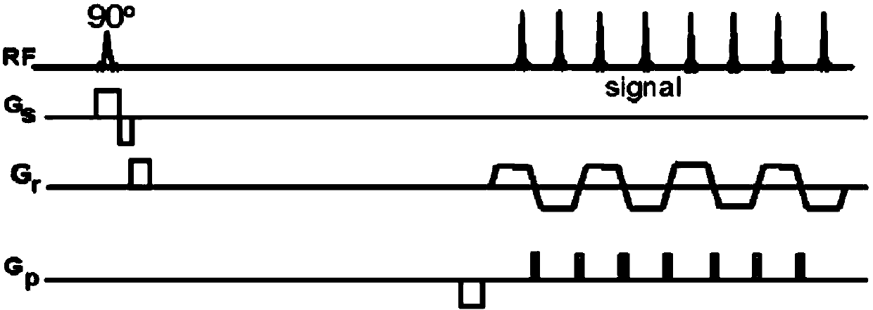
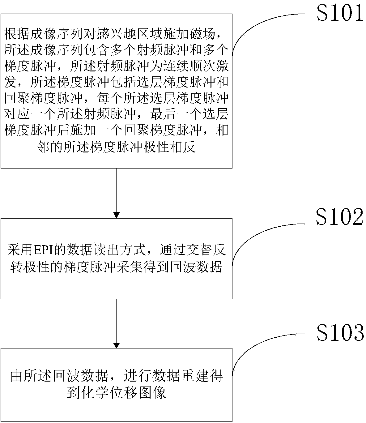
[0041] First, step S101 is executed to apply a magnetic field to the region of interest according to the imaging sequence. Figure 4 It is a schematic diagram of the EPCSI sequence of the echo-planar chemical shift imaging of the present invention. Among them, Gs and Gr respectively represent the gradient of the layer selection direction and the gradient of the readout direction, RF represents the radio frequency pulse, and signal represents the generated echo signal data. Its phase encoding PE direction does not apply any encoding gradient, and the echo signal data (signal) is collected during the echo interval and the plateau period of the readout gradient. The acquisition method is the same as that of the EPI data readout method. The readout gradient pulse acquisition is used to obtain echo data, and the resolution in the PE direction can be obtained by saturation bands or selective pulses.
[0042]Different from EPSI, the technical scheme of the present invention excites ...
Embodiment 2
[0051] In the first embodiment, three radio frequency pulses are applied in step S101, after which, the echo chain of the EPI is used for data collection, and the echo signal will be superimposed in the middle of the plateau period of the readout gradient. In order to separate the echo signals, preferably, after each layer-selection gradient pulse applied in step S101, a dephasing gradient pulse with a fixed size and duration is applied immediately in the readout direction, so that finally in Three separate echo signal data will be obtained for each plateau of the readout gradient. Such as Figure 5 shown, which is Figure 4 An enlarged view of the echo signal signal, where radio frequency pulses RF1, RF2, and RF3 correspond to echo signals 1, 2, and 3, respectively. Controlling the size of the readout gradient Gr or the bandwidth of the readout gradient can allow better separation of the three echoes.
[0052] After the dephasing gradient pulse is applied, the three echo s...
Embodiment 3
[0056] Also for the problem in the first embodiment that it is not easy to read the independent data due to the overlap of the echo signal data, if the phase of each radio frequency pulse is encoded, and then the overlapping echo signals are decoded, the individual data can be completely separated and obtained. Corresponding echo signal data.
[0057] When the spectrum data is collected without encoding the phase of the RF pulse, the phase of the RF pulse and the phase of the ADC receiver are often cycled and averaged due to some reasons in the system and the NMR signal itself. Such as Figure 7 As shown, taking 4 cycles as an example, when performing RF pulse excitation, the RF pulses with phases of 0°, 90°, 180° and 270° are used for cyclic excitation, and then the four samples collected in one cycle The echo signal data is averaged, so the number of echo signal acquisitions is a multiple of 4. For the convenience of description later, the aforementioned phase values of ...
PUM
 Abstract
Description
Claims
Application Information
 - R&D
- Intellectual Property
- Life Sciences
- Materials
- Tech Scout
- Unparalleled Data Quality
- Higher Quality Content
- 60% Fewer Hallucinations
Browse by: Latest US Patents, China's latest patents, Technical Efficacy Thesaurus, Application Domain, Technology Topic, Popular Technical Reports.
© 2025 PatSnap. All rights reserved.Legal|Privacy policy|Modern Slavery Act Transparency Statement|Sitemap|About US| Contact US: help@patsnap.com


