
Multi-effect decompression membrane distillation method and device thereof

A multi-effect membrane distillation and membrane distillation technology, which is applied in the field of decompression multi-effect membrane distillation methods and devices thereof, can solve the problems of low membrane distillation flux and the like, and achieve high membrane distillation flux, low energy consumption and high heat recovery rate. Effect

Inactive Publication Date: 2014-12-10
TIANJIN POLYTECHNIC UNIV
View PDF7 Cites 3 Cited by
  • Summary
  • Abstract
  • Description
  • Claims
  • Application Information

AI Technical Summary

Problems solved by technology

Therefore, the membrane distillation process requires a large amount of additional cooling water to condense the steam of the membrane distillation. If the feed liquid is used as the cooling water, the water vapor generated during the membrane distillation process is directly exchanged with the feed liquid through a heat exchanger, such as an air-gap membrane Distillation, the feed liquid cannot fully absorb the latent heat of steam. In order to increase the water production ratio, the temperature difference between the hydrophobic membrane surface and the heat exchange wall surface must be reduced, which leads to low membrane distillation flux.

Method used


Image

  • Multi-effect decompression membrane distillation method and device thereof
  • Multi-effect decompression membrane distillation method and device thereof

Examples


Embodiment Construction

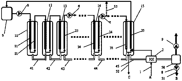
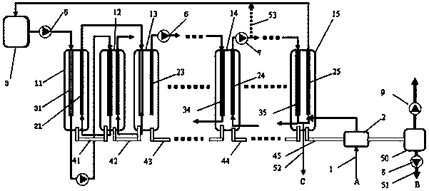
[0038] In the multi-effect membrane distillation method proposed by the present invention, multi-stage membrane distillation combination elements can be provided according to actual needs, but at least two stages are required. The following will be described according to the schematic diagram of the process flow of the multi-effect membrane distillation device of the present invention. figure 1 , figure 2 Both are schematic diagrams of the process flow of the multi-effect membrane distillation device of the present invention, and the pipeline connections of the two are slightly different.

[0039] Such as figure 1 As shown, the feed liquid coming out of the circulating heating water tank 3 has a temperature of 60 to 95°C, and is sent to the hydrophobic membrane flow path in the first-stage membrane distillation assembly element 11 through the circulating water pump 5, and flows through the hydrophobic membrane from top to bottom. The flow path 31, under the negative pressur...


PUM


Abstract

The invention provides a multi-effect decompression membrane distillation method and a device thereof. The device comprises multiple stages of membrane distillation combination elements, a circulating water pump, a vacuum pump, a circulating heating water tank, a heat exchanger, a water producing pump, a gas-liquid separation container and a connecting pipe, wherein a hydrophobic membrane with a top-down vertical flow path and a heat exchange pipe with a bottom-up vertical flow path are arranged in each membrane distillation combination element; feed liquid connecting pipes and water producing communicating pipes are arranged among the membrane distillation combination elements. The method comprises the following steps: when feed liquid flows past the flow path of the hydrophobic membrane of the membrane distillation combination elements, the feed liquid is subjected to membrane distillation under the action of negative pressure of a shell side; evaporated water vapor enters the shell side and is in contact with the pipe wall of the heat exchange pipe, heat of phase transition is released to be condensed to form membrane distillation producing water; after being evaporated and cooled, the unevaporated feed liquid in the flow path of the hydrophobic membrane flows past the heat exchange pipe; after absorbing heat for temperature rise, the feed liquid enters the flow path of the hydrophobic membrane of the next-stage membrane distillation combination element; by processing step by step, the feed liquid is concentrated step by step and then is discharged. Feed liquid concentration and full utilization of vaporization heat of phase transition are realized synchronously, and multi-effect decompression membrane distillation is completed.

Description

technical field [0001] The invention relates to a membrane distillation method and a device thereof, in particular to a decompression multi-effect membrane distillation method and a device thereof for water purification treatment, chemical industry separation of concentrated liquid and water desalination. Background technique [0002] Membrane distillation technology is a new type of liquid separation technology combined with membrane technology and traditional distillation technology. Compared with ordinary evaporators, one of the most notable features of membrane distillation is that the effective evaporation area per unit volume is large, so that the device can be used under normal pressure, It operates efficiently in the evaporation process at a lower temperature, and the equipment is made of plastic materials, which avoids the corrosion of metal materials under high salinity. Compared with reverse osmosis, membrane distillation is a heat-driven process with low operatin...

Claims


Application Information

Patent Timeline
IPC IPC(8): B01D61/36C02F1/04C02F1/44
CPCY02W10/37
Inventor 吕晓龙王晟林武春瑞高启君刘超王月
Owner TIANJIN POLYTECHNIC UNIV
Learn More