An electric dust removal device

A technology of electrostatic precipitator and rapping device, which is applied in the direction of electrode structure, electrostatic separation, electrode cleaning, etc. It can solve problems such as ash hopper falling off, electrostatic precipitator plate, pole line deformation, dust blocking or awning dust, etc., to achieve installation Easy to disassemble, avoid secondary pollution, and solve the effect of ash blocking problem

Active Publication Date: 2017-02-08
ZHEJIANG ZHUJI LIDA ENVIRONMENTAL PROTECTION EQUIP
View PDF16 Cites 0 Cited by
  • Summary
  • Abstract
  • Description
  • Claims
  • Application Information

AI Technical Summary

Problems solved by technology

In the actual operation of the electrostatic precipitator, the phenomenon of clogging or canopy ash often occurs in the ash hopper, which leads to poor ash transportation of the electrostatic precipitator and reduces the dust removal efficiency of the electrostatic precipitator
When the ash in the ash hopper or awning ash reaches the electrode plate of the electrostatic precipitator, it is easy to cause a short circuit in the electric field, which affects the safe operation of electrical equipment, and at the same time damages the internal components of the electrostatic precipitator, resulting in damage to the electrode plate and the electrode line of the electrostatic precipitator. deformation, etc., causing irreparable damage and possibly tripping the electric field
When the ash hopper is seriously accumulated, it may even cause the ash hopper to fall off and even the whole electrostatic precipitator to collapse

Method used


Image

  • An electric dust removal device
  • An electric dust removal device
  • An electric dust removal device

Examples


Embodiment Construction

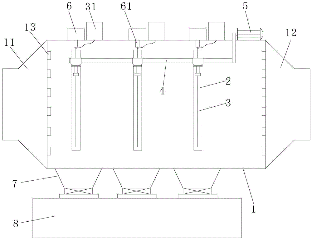
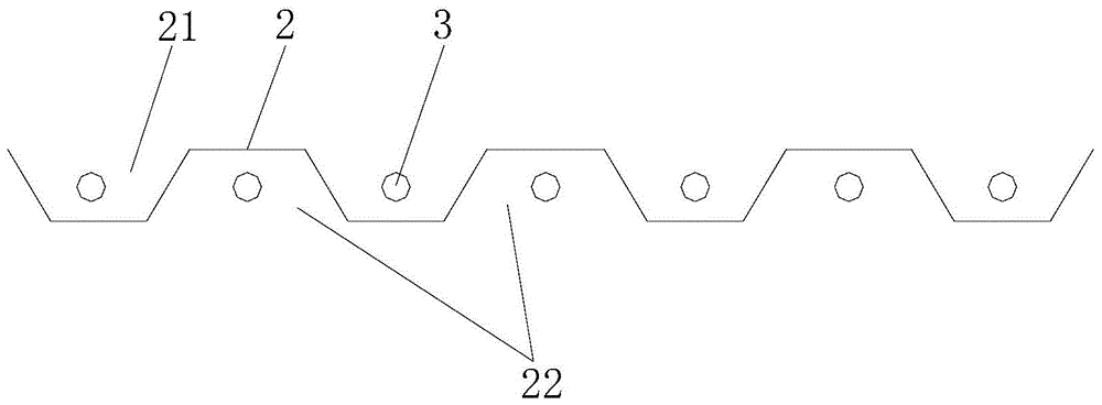
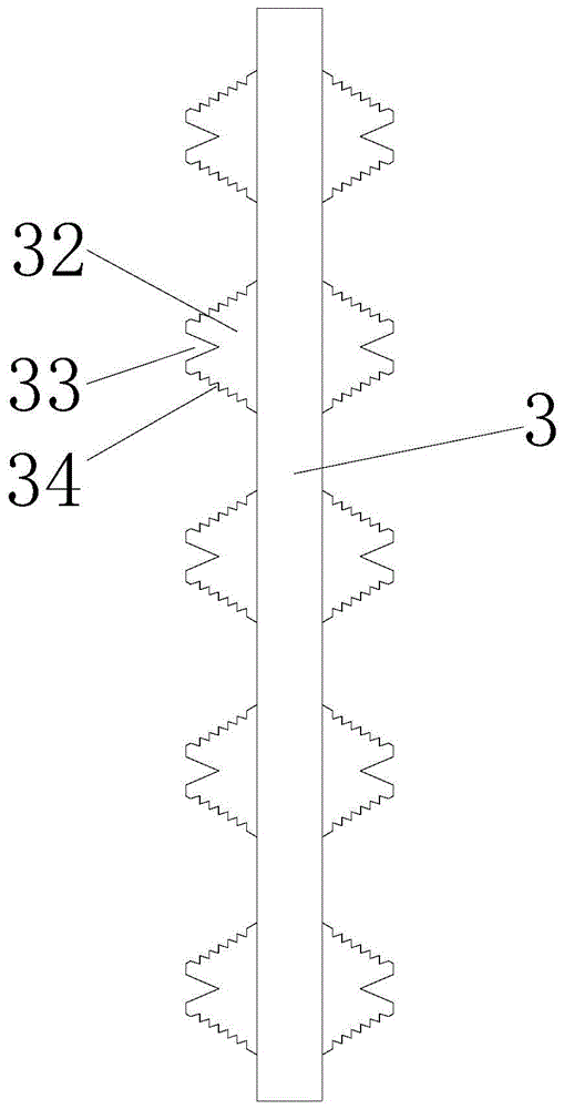
[0024] Refer to figure 1 , figure 2 , image 3 , Figure 4 with Figure 5 , An electric dust removal device of the present invention includes a box body 1, an anode plate 2, a corona wire 3, a rapping device 4, a motor 5, and a number of ash hoppers 7. An air inlet 11 is provided at one end of the box body 1, The other end of the box body 1 is provided with an exhaust port 12, a motor 5 and a number of suspension devices 6 are installed above the box body 1, and a plurality of insulating hangers 61 are installed below the suspension device 6, and each insulating hanger 61 is below A corona wire 3 is suspended, a transformer 31 is installed on one side of the suspension device 6, and the transformer 31 is connected to the corona wire 3. The anode plate 2 is correspondingly installed under the suspension device 6, and the anode plate 2 is arranged There are a number of corona wires 3, a rapping device 4 is installed on one side of the anode plate 2, and the rapping device 4 is c...


PUM


Abstract

The invention discloses an efficient electrical dust collector. The dust collector comprises a tank body, anode plates, corona wires, a rapping device, a motor and a plurality of ash buckets, wherein one end of the tank body is provided with an air inlet, and the other end of the tank body is provided with an exhaust port, the motor and a plurality of suspension devices are arranged above the tank body, a plurality of insulating hangs are arranged below the suspension devices and the corona wire is suspended below each insulating hang; a transformer is mounted at one side of each suspension device, and the transformers are connected with the corona wires; the anode plate is correspondingly arranged below each suspension device, and a plurality of corona wires are arranged in the anode plates, the rapping device is arranged at one sides of the anode plates, and the rapping device is connected with the motor; the plurality of ash buckets are arranged at the bottom of the tank body, one ash bucket is correspondingly arranged below each anode plate, the lower end of each ash bucket is provided with a cinder valve, the ash buckets are communicated with an ash storage tank through flanges, and an opening in the upper end of each ash bucket is communicated with the tank body. The efficient electrical dust collector disclosed by the invention is relatively high in dust removal rate and capable of preventing the secondary pollution.

Description

[0001] 【Technical Field】 [0002] The invention relates to the technical field of an electric dust removal device, in particular to the technical field of an electric dust removal device. [0003] 【Background technique】 [0004] Electrostatic precipitator is a necessary accessory equipment for thermal power plants. Its function is to remove particulate smoke and dust in the flue gas emitted by burning stoves or oil-fired boilers, thereby greatly reducing the amount of smoke and dust discharged into the atmosphere, which is to improve environmental pollution , An important environmental protection equipment to improve air quality. Its working principle is that when the flue gas passes through the flue in front of the main structure of the electrostatic precipitator, the flue dust is positively charged, and then the flue gas enters the electrostatic precipitator channel with multi-layer cathode plates. Due to the mutual adsorption of the positively charged soot and the cathode plate, ...

Claims


Application Information

Patent Timeline
Patent Type & Authority Patents(China)
IPC IPC(8): B03C3/09B03C3/76B03C3/41B03C3/34B03C3/88
CPCY02A50/2351
Inventor 苑举林俞利苗徐天飞俞建伟吴森行
Owner ZHEJIANG ZHUJI LIDA ENVIRONMENTAL PROTECTION EQUIP
Why Eureka
Try Eureka