
A New High Frequency Low Pass Filter with Stripline Structure

A low-pass filter and stripline technology, applied in the filter field, can solve the problems of small bandwidth and large loss, achieve low insertion loss, realize production cost, and improve the effect of cut-off frequency

Inactive Publication Date: 2017-05-17
NANJING UNIV OF SCI & TECH
View PDF5 Cites 0 Cited by
  • Summary
  • Abstract
  • Description
  • Claims
  • Application Information

AI Technical Summary

Problems solved by technology

However, the existing filters are not suitable for use in high-frequency bands, and the main constraints are small bandwidth and high loss

Method used


Image

  • A New High Frequency Low Pass Filter with Stripline Structure
  • A New High Frequency Low Pass Filter with Stripline Structure
  • A New High Frequency Low Pass Filter with Stripline Structure

Examples


Embodiment Construction

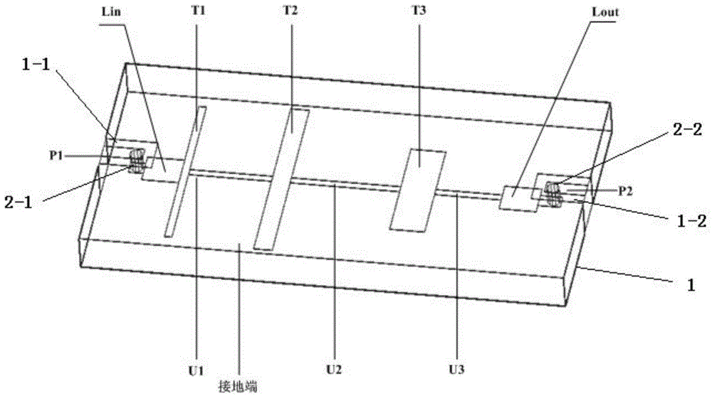
[0016] combine figure 1 , a high-frequency low-pass filter of a novel stripline structure, comprising a dielectric substrate 1, an input terminal P1 of a 50-ohm impedance of a coplanar waveguide structure, and an output terminal P2 of a 50-ohm impedance of a coplanar waveguide structure, characterized in that , also includes the input inductance L set in the cuboid dielectric substrate in , output inductance L out , and the first-level stripline T1, the second-level stripline T2, and the third-level stripline T3 located on the same plane:

[0017] The dielectric substrate 1 is in the shape of a cuboid, and its outer surface is a grounding terminal. The upper surface of the dielectric substrate 1 starts from the midpoint of one short side and extends toward the other short side. An input port opening 1-1 is set at the input port. In the opening 1-1; the upper surface of the dielectric substrate 1 starts from the midpoint of the other short side and extends toward the opposite...


PUM


Abstract

The invention provides a high-frequency low-pass filter with a strip line structure. The high-frequency low-pass filter comprises a dielectric substrate, an input terminal and an output terminal. The high-frequency low-pass filter is characterized in that the filter further comprises an input inductor, an output inductor, a first-level strip line, a second-level strip line and a third-level strip line, the input inductor and the output inductor are arranged in the cuboid dielectric substrate, the first-level strip line, the second-level strip line and the third-level strip line are positioned on the same plane, the strip lines are connected with one another through first-level circular strip lines, and the third-level strip line is connected with the output inductor through a first-level circular strip line. The novel high-frequency low-pass filter with the strip line structure, namely a low-pass filter with a new structure, is small in size, light in weight, high in reliability, excellent in electrical performance, simple in structure, high in yield and batch uniformity, low in cost and stable in temperature performance.

Description

[0001] 1. Technical field [0002] The invention relates to a filter, in particular to a high-frequency low-pass filter with a novel stripline structure. [0003] 2. Background technology [0004] In recent years, with the rapid development of miniaturization of mobile communication, satellite communication and national defense electronic systems, high performance, low cost and miniaturization have become the development direction of the microwave / radio frequency field. The performance, size and reliability of microwave filters Both sex and cost have put forward higher requirements. In some state-of-the-art national defense equipment, the current frequency band is quite crowded, and the frequency band of the low-pass filter is usually relatively low, so the low-pass filter of the micro-high frequency band has become a key electronic component in the receiving and transmitting branches of this band. However, the existing filters are not suitable for use in high-frequency bands,...

Claims


Application Information

Patent Timeline
Patent Type & Authority Patents(China)
IPC IPC(8): H01P1/203
Inventor 戴永胜许心影周衍芳陈龙顾家
Owner NANJING UNIV OF SCI & TECH
Learn More