Distortion calibration method for large field of view reflective free-form surface space camera

A space camera and distortion calibration technology, applied in measuring devices, instruments, etc., can solve problems such as unbearable cost and difficulty of development, incomplete compliance with prior laws, large size and weight of optical platforms, etc.

Active Publication Date: 2017-06-23
CHANGCHUN INST OF OPTICS FINE MECHANICS & PHYSICS CHINESE ACAD OF SCI
View PDF4 Cites 0 Cited by
  • Summary
  • Abstract
  • Description
  • Claims
  • Application Information

AI Technical Summary

Problems solved by technology

[0004] (1) The multispectral camera adopts the push-broom imaging method, while the three-dimensional test field calibration method, the two-step calibration method (RAC) based on radial constraints, and the multi-angle imaging method of the same calibration object are only suitable for staring imaging of area array detectors Distortion calibration of the system, so it is difficult to apply to the distortion calibration of the push-broom imaging system during the adjustment stage
[0005] (2) The calibration method based on the optical diffraction element requires a large-scale diffractive optical element whose aperture covers the optical system to be tested to provide incident light at different angles, and the effective aperture of the system to be tested exceeds 750mm, so it is currently difficult to process a suitable diffraction element
[0006] (3) The conventional precision angle measurement calibration method uses a turntable, a collimator and a standard calibration object to achieve precise measurement of distortion, but for a space camera with a 76° field of view, it is necessary to develop a collimator with a diameter of more than 1500mm to be able to use it during the rotation of the turntable. Covering the entire field of view, the development cost and difficulty are unbearable
[0007] (4) The precision angle measurement method needs to place the optical system on a high-precision turntable to provide a standard angle, but the integration and adjustment process of high-performance and complex optical systems is completed on the optical platform with the help of a large number of auxiliary adjustment equipment. The size and weight of the auxiliary assembly and adjustment equipment together with the optical table are too large to be placed on the turntable for distortion calibration
[0008] (5) For an imaging system composed of reflective free-form surface optical elements, its distortion distribution law does not fully conform to the existing distortion fitting a priori rules such as the least squares law, and it is difficult to use the current distortion fitting method to solve the full Distortion value of each point in the field of view

Method used


Image

  • Distortion calibration method for large field of view reflective free-form surface space camera
  • Distortion calibration method for large field of view reflective free-form surface space camera
  • Distortion calibration method for large field of view reflective free-form surface space camera

Examples


Embodiment Construction

[0046] The present invention will be further described in detail below in conjunction with the accompanying drawings.

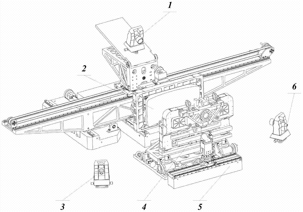
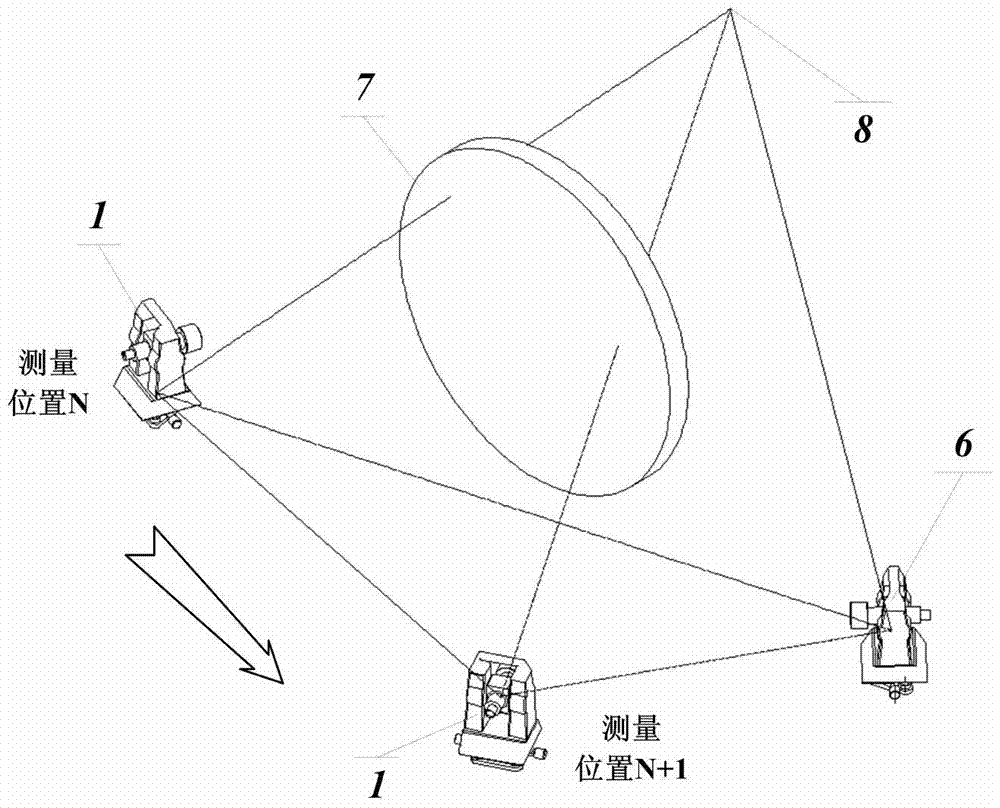
[0047] like Figure 1 to Figure 4 As shown, the distortion calibration method for a large field of view reflective free-form surface space camera of the present invention includes the following steps:

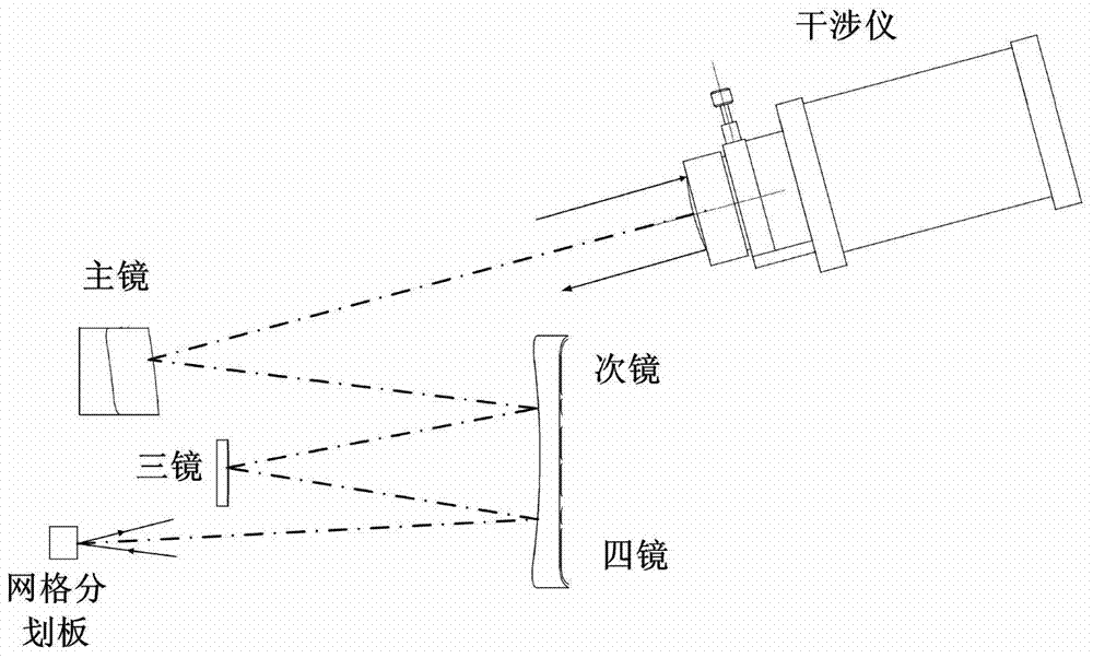
[0048] 1) Since the distortion calibration accuracy is closely related to the adjustment accuracy of the grid reticle 4 on the focal plane of the optical system 7 to be tested, it is necessary to firstly adjust the grid reticle with high precision on the focal plane of the optical system 7 to be tested. plate 4. first in figure 1 An optical interferometer equipped with a plane standard mirror is placed at the position of the measuring theodolite 1 shown, so that the interferometer, the optical system 7 to be measured, and the grid reticle 4 for scribing grid lines form a collimated interference optical path, such as figure 2 As shown, the principle of coll...


PUM


Abstract

The distortion calibration method of a reflective free-form surface space camera with a large field of view belongs to the field of optical detection and optical measurement technology. The method uses three theodolites to establish a measurement coordinate system, and calibrates the orientation of each measurement mark point in the full field of view of the optical system through benchmark conversion. Angle, pitch angle, and then use the data fitting method to realize the calibration of the two-dimensional distortion distribution of the reflective free-form surface optical system with a field of view of 76 degrees under the state of decentralized adjustment. The invention realizes the precision-guaranteed distortion measurement under the swing condition of the complex optical system, reduces the development cost and shortens the development cycle; the test results verify that the precision and accuracy of the above-mentioned measurement and data calculation methods all meet the development requirements.

Description

technical field [0001] The invention belongs to the technical field of optical detection and optical measurement, and in particular relates to a distortion calibration method of a large field of view reflective free-form surface space camera. Background technique [0002] The space remote sensor used for the census of crops on the ground needs to have a large field of view, so that the width of the ground mow corresponding to the satellite's one-time overhead can meet the demand for observation data such as crop growth. For this reason, the main optical load of the remote sensor, the very wide coverage multispectral space camera (hereinafter referred to as the space camera), uses multiple reflective free-form surface optical elements to form an optical system, which can reach a field of view of 76°, but this causes The distortion is up to 10% (theoretical value) in the imaging direction. The above distortion will cause image distortion and distortion, resulting in the diffe...

Claims


Application Information

Patent Timeline
Patent Type & Authority Patents(China)
IPC IPC(8): G01C25/00
CPCG01C25/00
Inventor 何煦张晓辉吴国栋曹智睿
Owner CHANGCHUN INST OF OPTICS FINE MECHANICS & PHYSICS CHINESE ACAD OF SCI
Why Eureka
Try Eureka