Manufacturing method of field-effect regulated supercapacitor

A supercapacitor and field effect technology, applied in the field of capacitors, can solve the problems of high manufacturing cost, complex manufacturing process, and poor method universality.

Active Publication Date: 2014-12-17
WUHAN UNIV OF TECH
View PDF3 Cites 5 Cited by
  • Summary
  • Abstract
  • Description
  • Claims
  • Application Information

AI Technical Summary

Problems solved by technology

The preparation process of the above improved methods is complicated, the production cost is high, and the method has poor universality

Method used


Image

  • Manufacturing method of field-effect regulated supercapacitor
  • Manufacturing method of field-effect regulated supercapacitor
  • Manufacturing method of field-effect regulated supercapacitor

Examples


preparation example Construction

[0020] The preparation process of the field effect regulation supercapacitor of the present invention:

[0021] Deposit a layer of dielectric layer material on the substrate; disperse the electrode material on the dielectric layer material; coat the resist on the dielectric layer and channel to prepare a source, drain and capacitor electrode; coating photoresist on the source electrode and the drain electrode; encapsulating with polydimethylsiloxane as a whole, injecting electrolyte solution, and obtaining a field effect control supercapacitor.

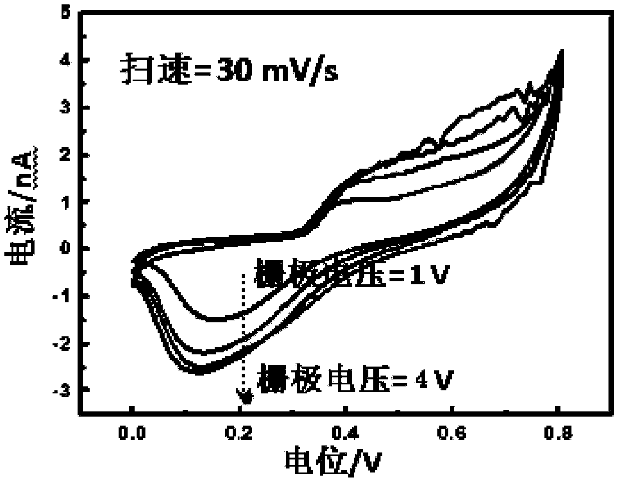
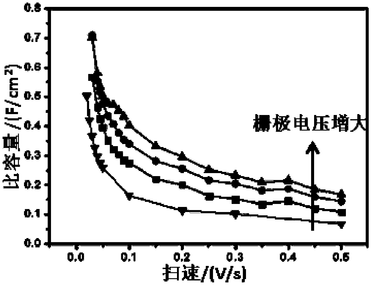
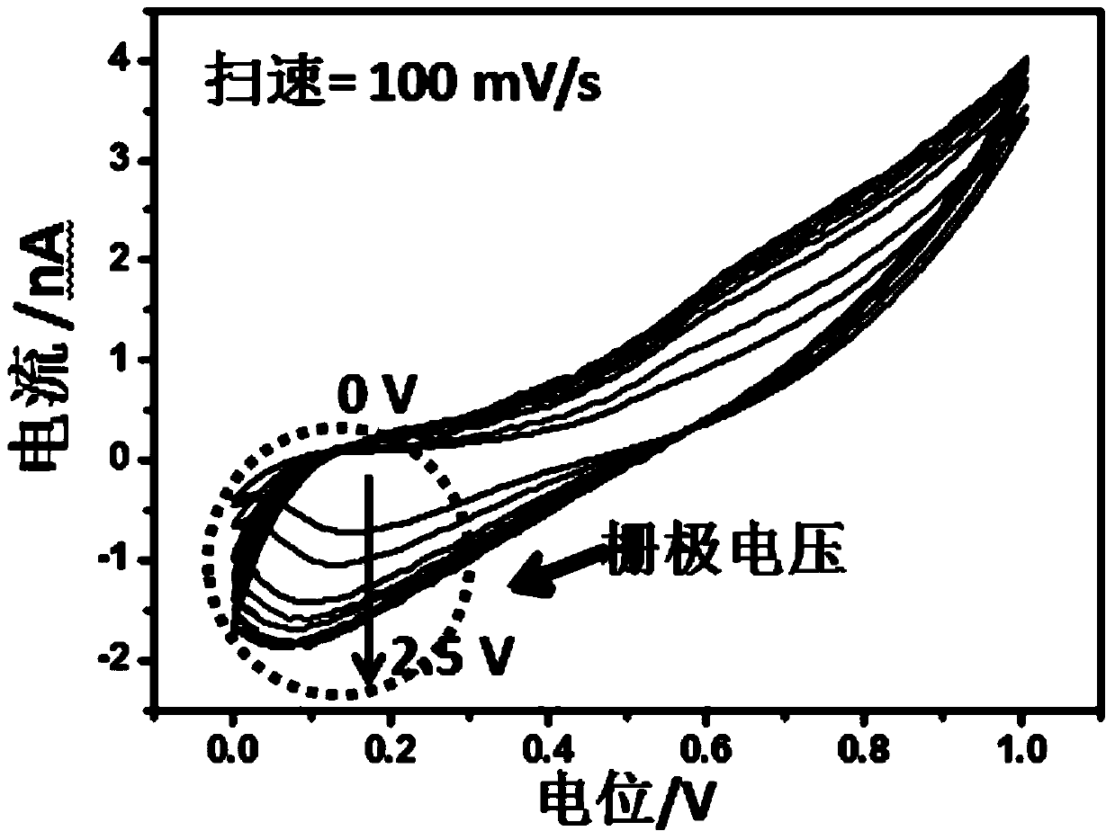
[0022] The energy storage device is optimized by changing the carrier distribution and conductivity of the material itself through the external field effect. Under the regulation of the gate electric field, the capacity of the supercapacitor is increased by an average of 3 to 5 times, and the original capacity is maintained. rate performance.

Embodiment 1

[0024] 1) Select a silicon substrate with a 300nm thermal oxide layer, cut the silicon substrate into an appropriate size, then ultrasonically clean the silicon substrate with isopropanol (IPA) for about 30 seconds, and dry it with nitrogen.

[0025] 2) Use a spin coater to spin coat a layer of MMA on the substrate, the spin coating speed is 4000rpm, the spin coating time is 90s, use a hot plate to bake, 180°C, 5min; then spin coat a layer of PMMA on the substrate, The rotational speed of the spin coating is 4000rpm, the spin coating time is 90s, and a hot plate is used for baking at 180°C for 5min.

[0026] 3) Etch the pattern of external electrodes and marks on the spin-coated silicon wafer using an electron beam exposure machine (EBL), with an exposure dose of 380 μC / cm 2 , the electron beam accelerating voltage is 30kV, and the electron beam current is 400pA.

[0027] 4) Developing: soak the substrate after electron beam exposure in methyl isobutyl ketone (MIBK) solution ...

Embodiment 2

[0047] Preparation process of field-effect regulated supercapacitor nanodevices:

[0048] Select a silicon substrate and use ALD to deposit Al with a thickness of 80nm 2 o 3 , as a dielectric layer.

[0049] Use a spin coater to spin-coat a layer of MMA on the substrate, the spin-coating speed is 4000rpm, the spin-coating time is 90s, use a hot plate to bake, 180°C, 5min; then spin-coat a layer of PMMA on the substrate, spin-coat The rotating speed is 4000rpm, the spin-coating time is 90s, and baked on a hot plate at 180°C for 5min.

[0050] Use electron beam exposure machine (EBL) to etch the pattern of external electrodes and marks on the spin-coated silicon wafer, the exposure dose is 380μC / cm 2 , the electron beam accelerating voltage is 30kV, and the electron beam current is 400pA.

[0051] Developing: soak the substrate after electron beam exposure in methyl isobutyl ketone (MIBK) solution for 1 min, then in isopropanol for 30 s, and blow dry with nitrogen.

[0052] P...


PUM


Abstract

The invention discloses a manufacturing method of a field-effect regulated supercapacitor. The manufacturing method includes the steps of depositing a layer of dielectric material on a substrate; spreading electrode material on the dielectric material; coating the dielectric material and trenches with resist to obtain a source, a drain and an electrode of the supercapacitor; coating the source and the drain with photoresist; performing overall packaging with polydimethylsiloxane, and pouring in electrolyte to obtain the field-effect regulated supercapacitor. A concept to increase energy density of the supercapacitor is provided, namely carrier distribution and conductivity of material are changed via additional field effect so that an energy storage device is optimized; under regulating action of a gate electric field, the capacity of the supercapacitor is averagely increased by three times to five times, and original rate performance is retained.

Description

technical field [0001] The invention belongs to the technical field of capacitors, and in particular relates to a preparation method of a field-effect regulated supercapacitor. Background technique [0002] Supercapacitor is a new type of energy storage device developed in the 1970s and 1980s between batteries and traditional capacitors. It has a large capacitance of Farad level, which is 2000-6000 times larger than that of electrolytic capacitors of the same volume. The power density is 10-100 times higher than that of batteries, and it has a longer cycle life. It is considered to be an efficient and practical new type of clean energy. It is currently used as a backup power supply and is widely used in electronic devices such as cameras, video recorders, mobile phones, and computers. product. [0003] According to different energy storage mechanisms, supercapacitors can be divided into electric double layer capacitors and pseudocapacitors. The generation of electric doubl...

Claims


Application Information

Patent Timeline
Patent Type & Authority Applications(China)
IPC IPC(8): H01G11/84
CPCY02E60/13
Inventor 麦立强王佩瑶双逸晏梦雨
Owner WUHAN UNIV OF TECH
Why Eureka
Try Eureka