Topological structure of photovoltaic power station system based on bipolar direct-current transmission

A technology for DC transmission and photovoltaic power plants, applied in photovoltaic power generation, conversion of AC power input to DC power output, output power conversion devices, etc., can solve the problem of reducing system reliability, power device heating, line loss and cost increase, etc. problem, to achieve the effect of improving the utilization rate of DC voltage, increasing the switching frequency, and increasing the inverter capacity

Active Publication Date: 2014-12-17
周细文 +1
View PDF2 Cites 22 Cited by
  • Summary
  • Abstract
  • Description
  • Claims
  • Application Information

AI Technical Summary

Problems solved by technology

[0004] Now the mainstream photovoltaic inverters of photovoltaic power plants are mostly low-voltage systems of 270V or 315V. Due to the limitation of the device current level and the input cost of power station cables, the starting voltage of the inverter is generally 450V or 500V, which makes it difficult to fully utilize the voltage of the photovoltaic array; the general photovoltaic power station adopts a unipolar topology, that is, each 500kW positive pole and negative pole each have 2 root 240mm 2 cables (take direct buried soil as an example)
[0005] A single large-scale photovoltaic power station has multiple inverters, which belong to different manufacturers. The DC system topology of existing photovoltaic power stations mostly adopts unipolar type. Taking the traditional MW-level photovoltaic inverter system topology as an example, in order to improve the inverter The power level of the converter, if the parallel connection of converters is used, it is easy to cause the circulation problem, the circulation flows between the parallel converters, its existence increases the loss, reduces the system efficiency, causes the power device to heat up seriously, and even burns out
[0006] At present, two methods are often used to solve the circulating current problem in the parallel converter system: one is to eliminate the circulating current channel on the hardware, and the other is to use an appropriate control method to suppress the circulating current; usually the method of eliminating the circulating current by hardware is to add an isolation transformer. The isolation transformer can block the circulating current circuit on the AC side and eliminate the circulating current. At the same time, the isolation transformer with different forms of secondary structure can eliminate specific harmonics and reduce the pollution to the power grid. The use of appropriate control methods to suppress the circulating current will usually cause The control and measurement system is complicated; if one of the multiple sets of direct parallel connection has a short-circuit fault, the other parallel branches must be protected, thereby reducing the reliability of the system; in addition, the capacity of the inverter is large, and the AC and DC voltage levels are different. Lower, the required DC or AC transmission cables or busbars increase, and the line loss and cost will also increase

Method used


Image

  • Topological structure of photovoltaic power station system based on bipolar direct-current transmission
  • Topological structure of photovoltaic power station system based on bipolar direct-current transmission
  • Topological structure of photovoltaic power station system based on bipolar direct-current transmission

Examples


Embodiment Construction

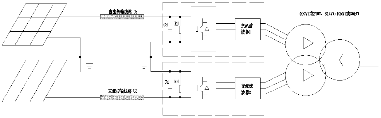
[0043] Such as figure 1 As shown, in the present invention, the +Ud side inverter and the -Ud side inverter can respectively use parallel connection of inverter circuits of different power levels, so as to realize different topology structures of photovoltaic power generation systems, and the basic principles of various circuit topology structures are similar. There is only a difference in the inverter circuit. The circuit is composed of the following parts: photovoltaic arrays used in series and parallel, DC transmission lines, photovoltaic inverters, AC filters and grid-connected transformers;

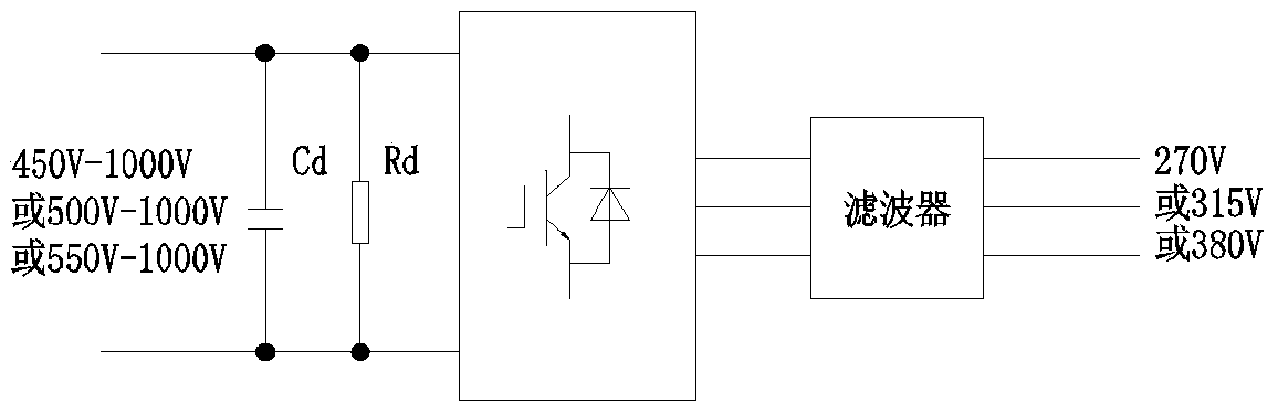
[0044] Such as figure 2 As shown, the inverter is a single-stage photovoltaic inverter, which can achieve AC output of 270V or 315V or 380V according to the different starting voltages. This type of inverter has high efficiency and can reach more than 98.5%, but it cannot achieve wide Range DC input to improve the DC voltage utilization of the PV array, so it is not ideal;
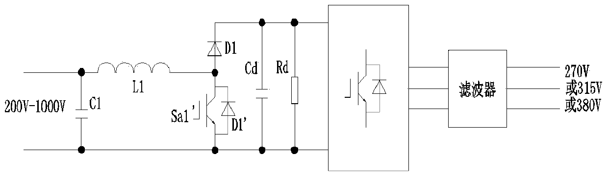
[0045...


PUM


Abstract

The invention discloses a topological structure of a photovoltaic power station system based on bipolar direct-current transmission. The topological structure of the photovoltaic power station system based on bipolar direct-current transmission comprises a positive direct-current transmission line, a negative direct-current transmission line, two groups of photovoltaic inverters which are connected in parallel, and a boosting transformer, wherein each group of photovoltaic inverters comprises a Boost circuit, a direct-current bus, a three-phase bridge inverter and an alternating-current filter which are sequentially arranged along a direct-current transmission direction, and the output ends of the two groups of photovoltaic inverters are connected to the a boost transformer. The topological structure of the photovoltaic power station system based on bipolar direct-current transmission designed by the invention is capable of running simultaneously, and running singly and independently, thus the running reliability is enhanced, a high-power photovoltaic inverter is applicable, the power generation efficiency of a photovoltaic array is further increased, the input range of the direct-current voltage of the inverter is expanded, and the utilization rate of the direct-current voltage of the photovoltaic array is increased; two paths of output are connected with two three-phase windings of a grid-connected transformer, thus the switching frequency can be equivalently increased, and the harmonic waves of a grid-connected current can be reduced.

Description

technical field [0001] The invention relates to the field of photovoltaic power generation, in particular to a photovoltaic power station system topology based on bipolar direct current transmission. Background technique [0002] As a sustainable clean energy, solar energy has great potential for development and application. 76% of my country's land is full of sunlight, and the distribution of light energy resources is relatively uniform. Compared with hydropower, wind power, nuclear power, etc., solar power generation does not have any emissions and noise pollution. , the application technology is mature, safe and reliable; in addition to large-scale grid-connected power generation and off-grid applications, solar energy can also be stored in various ways such as pumping water, superconducting, storage batteries, and hydrogen production. Solar energy storage can almost meet China's future stable energy needs. need. [0003] With the changes in the world's energy pattern, pho...

Claims


Application Information

Patent Timeline
Patent Type & Authority Applications(China)
IPC IPC(8): H02J3/38H02M7/537H02M1/12
CPCY02E10/56
Inventor 周细文周金博张伟
Owner 周细文
Why Eureka
Try Eureka