Supercharge Your Innovation With Domain-Expert AI Agents!

Mechanical seal with two-stage staggered hydrodynamic grooves

A fluid dynamic pressure and mechanical sealing technology, applied in the direction of engine seals, mechanical equipment, engine components, etc., can solve the problem of not verifying the end face opening performance and sealing ability of the end face structure, not solving the wear of particles on the dynamic pressure groove, and not having good performance. The ability to excrete particles and other issues can enhance the effect of convective heat transfer, improve friction and lubrication, and enhance the dynamic pressure effect and pumping effect.

Inactive Publication Date: 2014-12-24
JIANGSU UNIV
View PDF11 Cites 7 Cited by
  • Summary
  • Abstract
  • Description
  • Claims
  • Application Information

AI Technical Summary

Problems solved by technology

Chinese patents 103133696A and 102518809A disclose a mechanical seal ring structure that can automatically discharge particles and prevent solid particle inhalation, but it has not been verified whether the modified end face structure still has better end face opening performance and sealing ability
Chinese patent 2534428Y discloses a hydrodynamic pressure groove sealing structure with staggered lengths, but it still does not solve the problem of particle wear on the dynamic pressure groove
Chinese patent 2442034Y introduces a double-row reverse hydrodynamic groove self-lubricating non-contact mechanical seal, but it still has low sealing ability and no good ability to discharge particles
EP0564153A1 discloses a non-contact mechanical seal with double-row spiral grooves, which has better starting performance and solid particle prevention ability, but its sealing ability is low and its application range is limited

Method used


Image

  • Mechanical seal with two-stage staggered hydrodynamic grooves
  • Mechanical seal with two-stage staggered hydrodynamic grooves
  • Mechanical seal with two-stage staggered hydrodynamic grooves

Examples


Embodiment Construction

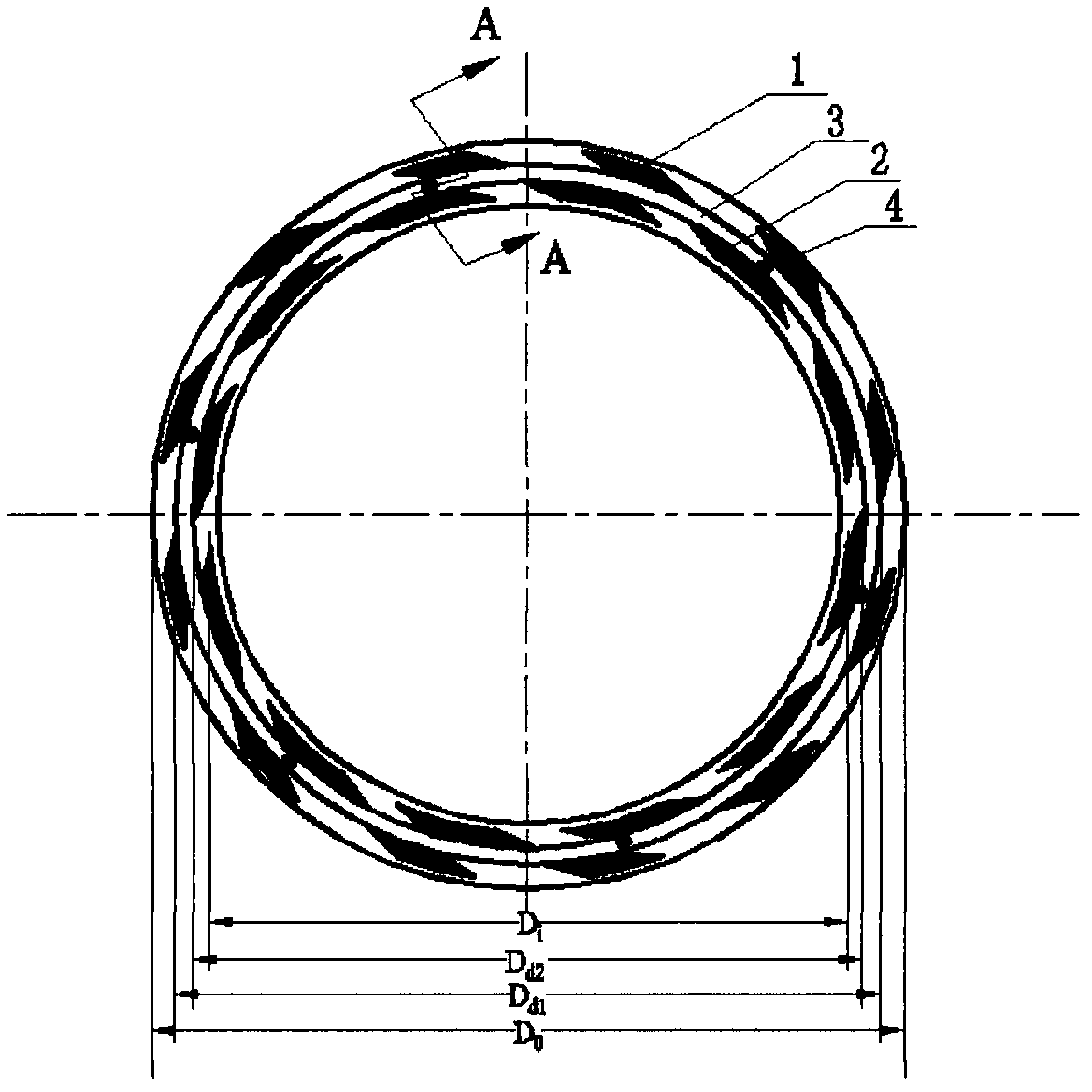
[0011] The double-stage dynamic pressure groove and flow guide groove 3 in the present invention are all opened on the mechanical seal dynamic ring, and the end surface modification can be processed by electric spark, electrochemical corrosion, laser processing and other processes.

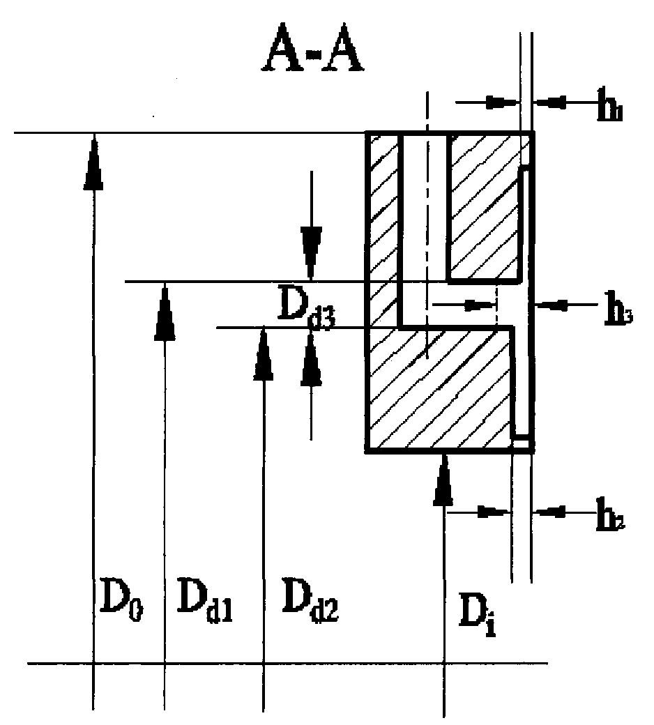
[0012] The first-stage dynamic pressure groove 1, the diversion groove 3 and the second-stage dynamic pressure groove 2, which are symmetrically distributed in the circumferential direction, are set up in the radial direction on the end face of the dynamic ring of the mechanical seal. The diversion groove 3 and the double-stage dynamic pressure groove are respectively connected connection, such as figure 1 As shown, the shape line of the two-stage dynamic pressure groove is a logarithmic helix, the helix angle θ=21°, the width ratio of the groove and weir γ=1.5, and the first-stage dynamic pressure groove is 1 groove deep h 1 =3μm, second stage dynamic pressure groove 2 groove depth h 2 =5μm, gro...


PUM

PropertyMeasurementUnit
Groove depthaaaaaaaaaa

Abstract

The invention relates to a mechanical seal ring structure with two-stage staggered hydrodynamic grooves. Primarily, two-stage staggered directional hydrodynamic grooves are circumferentially formed in a seal moving ring or static ring; an annular flow guide groove is formed between the two-stage hydrodynamic grooves and is connected with the two-stage hydrodynamic grooves respectively; a through hole which is connected with a seal cavity is formed in the flow guide groove; thus, good sealing property and automatic particle discharge capacity of the non-contact mechanical seal are realized, the blockage of the hydrodynamic grooves is prevented, and the wear and the thermal deformation of sealing end faces are reduced; the seal ring can adapt to the working condition containing a solid granule medium.

Description

technical field [0001] The invention relates to fluid mechanical seal technology and fluid dynamic pressure lubrication theory, specifically a new non-contact mechanical seal structure with double-stage staggered fluid dynamic pressure grooves. Background technique [0002] Non-contact end face mechanical seals are widely used in aerospace, nuclear power, petrochemical and other industries. In order to reduce end face wear and leakage, various mechanical seals using hydrodynamic and static pressure effects and pumping effects have emerged. In the occasions of conveying petroleum and chemical industry containing particles and many impurities, tiny solid particles will enter between the sealing end faces. If they cannot be removed in time, the micro-molding of the sealing end faces will be blocked and invalid, and the dynamic pressure effect of the dynamic pressure groove cannot be exerted. At the same time The presence of particles can also produce abrasive wear, which can l...

Claims


Application Information

Patent Timeline
IPC IPC(8): F16J15/40F16J15/16
Inventor 吴强波陈汇龙徐成左木子
Owner JIANGSU UNIV
Features
  • R&D
  • Intellectual Property
  • Life Sciences
  • Materials
  • Tech Scout
  • Unparalleled Data Quality
  • Higher Quality Content
  • 60% Fewer Hallucinations
Learn More