Method for reducing SO2 emission concentration of sulfur recovery device

A technology for emission concentration and sulfur recovery, applied in separation methods, chemical instruments and methods, sulfur preparation/purification, etc., can solve problems such as sulfur recovery and emission not up to standard

Active Publication Date: 2014-12-31
CHINA PETROLEUM & CHEM CORP
View PDF3 Cites 50 Cited by
  • Summary
  • Abstract
  • Description
  • Claims
  • Application Information

AI Technical Summary

Problems solved by technology

[0008] In order to solve the above-mentioned technical problems, the present invention proposes a process with low investment and low operating cost to reduce the sulfur recovery unit flue gas SO 2 emission concentration, to solve SO in the existing sulfur recovery 2 Technical problems of non-compliance with emission standards

Method used


Image

  • Method for reducing SO2 emission concentration of sulfur recovery device
  • Method for reducing SO2 emission concentration of sulfur recovery device
  • Method for reducing SO2 emission concentration of sulfur recovery device

Examples


Embodiment 1

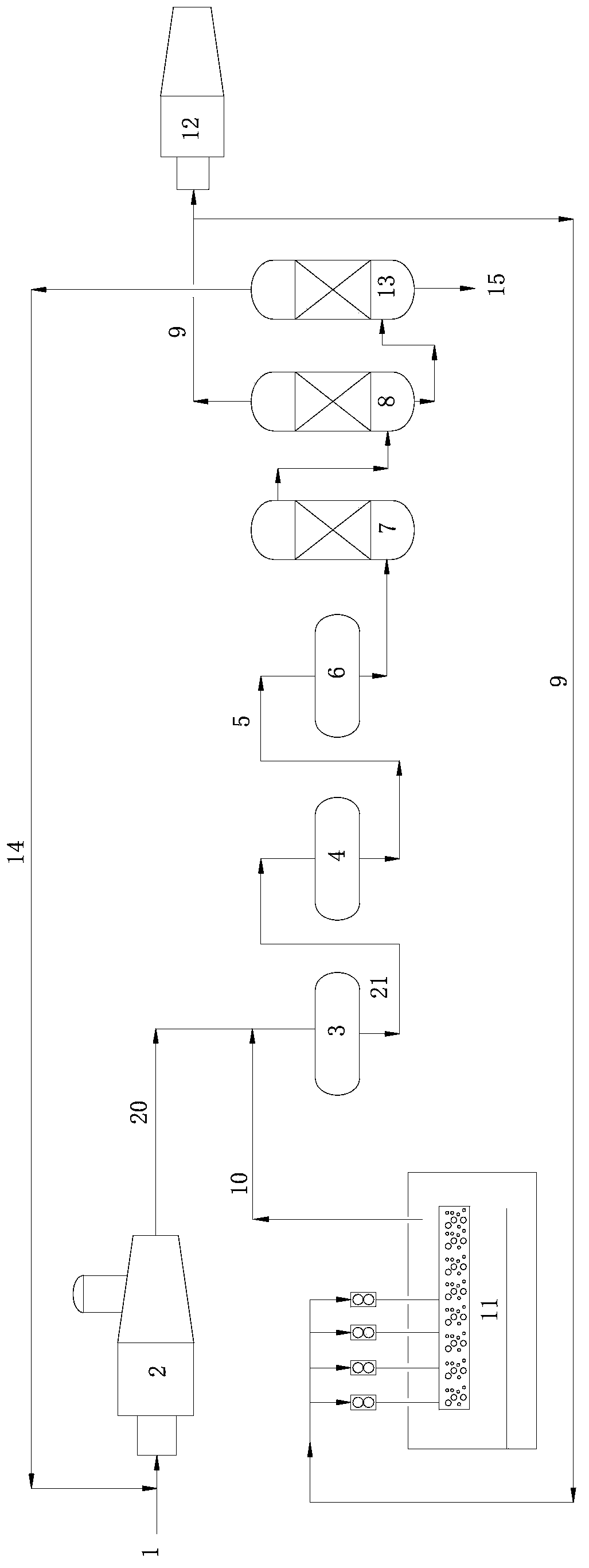
[0052] process such as figure 1 As shown, it includes thermal reaction stage, catalytic reaction stage and exhaust gas purification treatment stage.

[0053] 1) Thermal reaction stage:

[0054] Contains H 2 S: 92 (v / v)% acid gas (1) is partially combusted into SO in the reactor (2) 2 , at the furnace combustion temperature of 1250°C, H 2 S and SO 2 A Claus reaction occurs to generate elemental sulfur and reaction furnace tail gas (20), the elemental sulfur condenses and enters the liquid sulfur pool (11) to recover liquid sulfur, and the reaction furnace tail gas (20) enters the catalytic reaction stage. Reactor tail gas (20) volume content of sulfur compounds is: H 2 S: 8.2%, SO 2 : 4.2%, organic sulfur: 0.5%.

[0055] 2) Catalytic reaction stage:

[0056] Reactor tail gas (20) enters the primary converter (3) in the catalytic reaction stage (reaction conditions: temperature 300°C, space velocity 800h -1 ), react under the action of catalyst to generate elemental sul...

Embodiment 2

[0062] Except following difference, other is with embodiment 1.

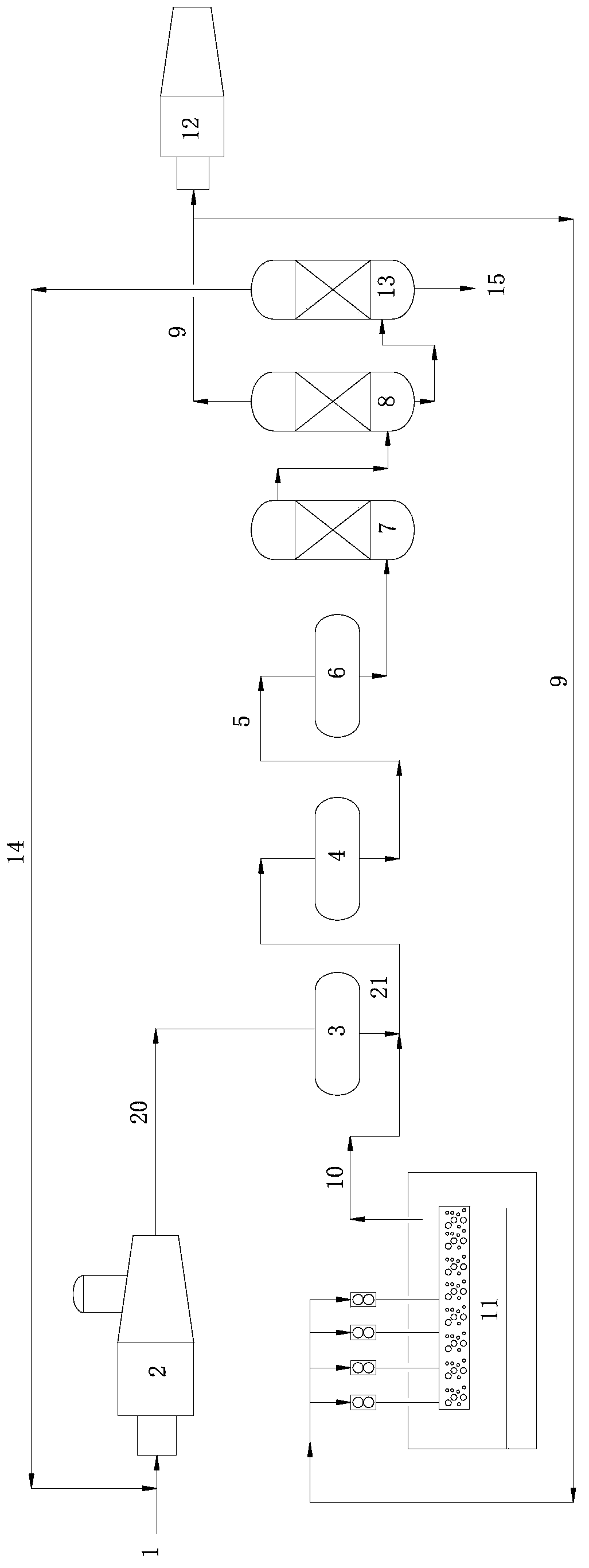
[0063] process such as figure 2 shown.

[0064] 2) Catalytic reaction stage:

[0065] The catalyst loading scheme is to fill the upper part of the primary converter and the secondary converter with a half-height LS-981 multi-functional sulfur recovery catalyst with oxygen leakage function, and the lower part is filled with a half-height LS-02 large specific surface area oxidation catalyst Aluminum based sulfur recovery catalyst. Claus tail gas (5) sulfur compound volume content is: H 2 S: 1.4%, SO 2 : 0.6%, organic sulfur: 0.08%.

[0066] 3) Exhaust gas purification treatment stage:

[0067] The liquid sulfur degassed waste gas (10) from the liquid sulfur tank (11) is mixed with the tail gas of the primary converter (21) and enters the secondary converter (3) for treatment; the amine liquid absorbing hydrogen sulfide enters the regeneration tower (13) for regeneration , regeneration acid gas (14)H 2 The...

Embodiment 3

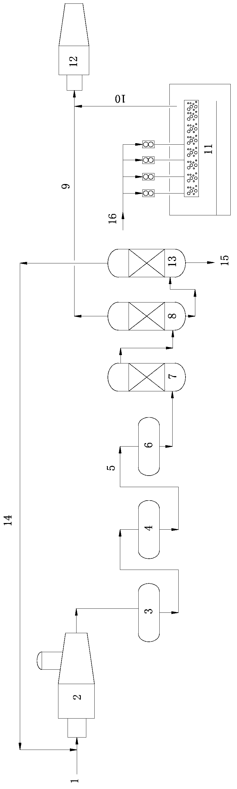
[0069] Except following difference, other is with embodiment 1.

[0070] 1) Thermal reaction stage:

[0071] Contains H 2 S: 85 (v / v)% acid gas (1) is partially combusted into SO in the reactor (2) 2 .

[0072] Reactor tail gas (20) volume content of sulfur compounds is: H 2 S: 7.2%, SO 2 : 3.5%, organic sulfur: 0.4%.

[0073] 2) Catalytic reaction stage:

[0074] The catalyst loading scheme is that the upper part of the primary converter is filled with LS-981 multi-functional sulfur recovery catalyst with oxygen leakage function, and the lower part is filled with LS-02 large specific surface area alumina-based sulfur recovery catalyst with two-thirds height ; The secondary converter is fully filled with LS-02 large specific surface area alumina-based sulfur recovery catalyst. Claus tail gas (5) sulfur compound volume content is: H 2 S: 1.4%, SO 2 : 0.6%, organic sulfur: 0.1%.

[0075] 3) Exhaust gas purification treatment stage:

[0076] The amine liquid absorbing ...


PUM

PropertyMeasurementUnit
specific surface areaaaaaaaaaaa

Abstract

The invention relates to a method for reducing the SO2 emission concentration of a sulfur recovery device. The method includes: at a tail gas purification processing stage, subjecting Claus tail gas to hydrogenation reaction, quench tower cooling and amine liquid absorption in turn, then taking part of purification tail gas as the stripping gas for liquid sulfur degassing, leading the residual purification tail gas into an incinerator to incinerate, letting the exhaust gas of liquid sulfur degassing enter a catalytic reaction stage, making the amine liquid absorbing hydrogen sulfide enter a regeneration tower to undergo regeneration, mixing a regenerated acidic gas with a raw material acidic gas, and returning the mixture to the thermal reaction section again for further recovery of elemental sulfur. The method for reducing the SO2 emission concentration of the sulfur recovery device provided by the invention is efficient, energy saving and economical, and greatly reduces the SO2 emission concentration.

Description

technical field [0001] The invention belongs to the technical field of sulfur recovery, in particular, relates to a sulfur recovery device for reducing SO 2 method of emission concentration. Background technique [0002] With the development of society, the problem of environmental pollution has become a restrictive factor for the rapid economic development, and it is an important and indispensable content of the legislation of governments in various countries. Industrially developed countries have very strict requirements on sulfur emissions. The United States Federal Government Environmental Protection Agency regulations stipulate that industrial heating furnace flue gas, sulfur tail gas and catalytic cracking regeneration flue gas SO 2 The emission concentration limit is 50ppm (v), equivalent to about 143mg / m 3 . Foreign countries have been studying the new technology of Claus method sulfur recovery tail gas treatment. In 2007, the United States published a process pa...

Claims


Application Information

Patent Timeline
Patent Type & Authority Applications(China)
IPC IPC(8): C01B17/04B01D53/86B01D53/50B01D53/14
CPCY02P20/50
Inventor 达建文刘爱华张义玲刘剑利陶卫东刘增让张艳松
Owner CHINA PETROLEUM & CHEM CORP
Why Eureka
Try Eureka