
Dust and waste gas treatment device

A technology for waste gas treatment device and dust, applied in the field of environmental treatment, can solve the problems of increased floor space of treatment device facilities, difficulty in meeting emission standards, inconvenient operation and management, low daily operation and maintenance costs, and reduced treatment investment costs. , the effect of simple equipment and process operation

Inactive Publication Date: 2015-01-07
ZUNYI TIANLI ENVIRONMENTAL ENG
View PDF8 Cites 10 Cited by
  • Summary
  • Abstract
  • Description
  • Claims
  • Application Information

AI Technical Summary

Problems solved by technology

[0003] At present, most of the treatment methods for this kind of dust waste gas use the process of multi-stage joint treatment to carry out environmental protection treatment of dust and waste gas generated by flue gas polluting enterprises, that is, the treatment of waste gas and dust is generally carried out in different treatment systems. Although the process of segmented multi-stage combined treatment achieves the purpose of treating waste gas or dust up to the standard, the area occupied by the treatment device is enlarged, the operation and management are inconvenient, the equipment investment cost is large, the treatment process is long, and the treatment cost is high. In addition, in the present In some dust treatment processes, due to the limitation of equipment structure and treatment effect, it is difficult to reach 100mg / m 3 emission standards

Method used


Image

  • Dust and waste gas treatment device
  • Dust and waste gas treatment device

Examples


Embodiment Construction

[0018] The present invention will be described in further detail below in conjunction with accompanying drawing, but should not be interpreted as that the scope of the subject matter of the present invention is limited to following embodiment, under the situation of not departing from above-mentioned technical idea of ​​the present invention, all according to the common technical knowledge of this field and Various modifications, substitutions and alterations made by conventional means are included within the scope of the present invention.

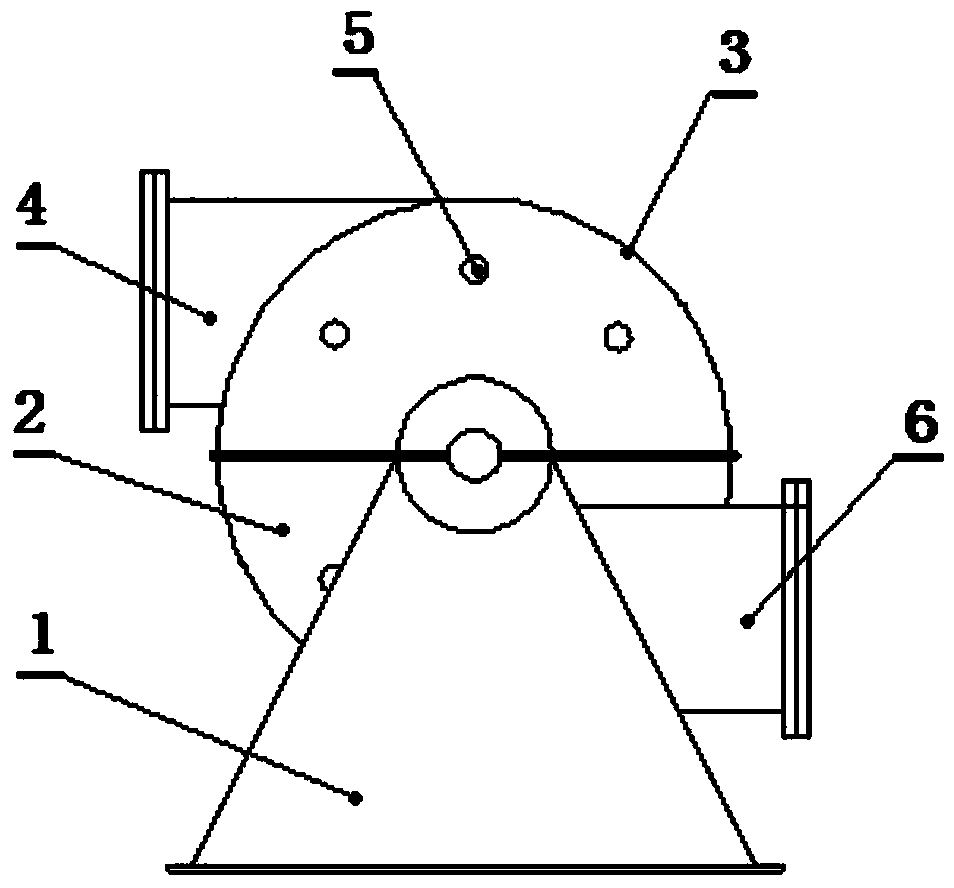
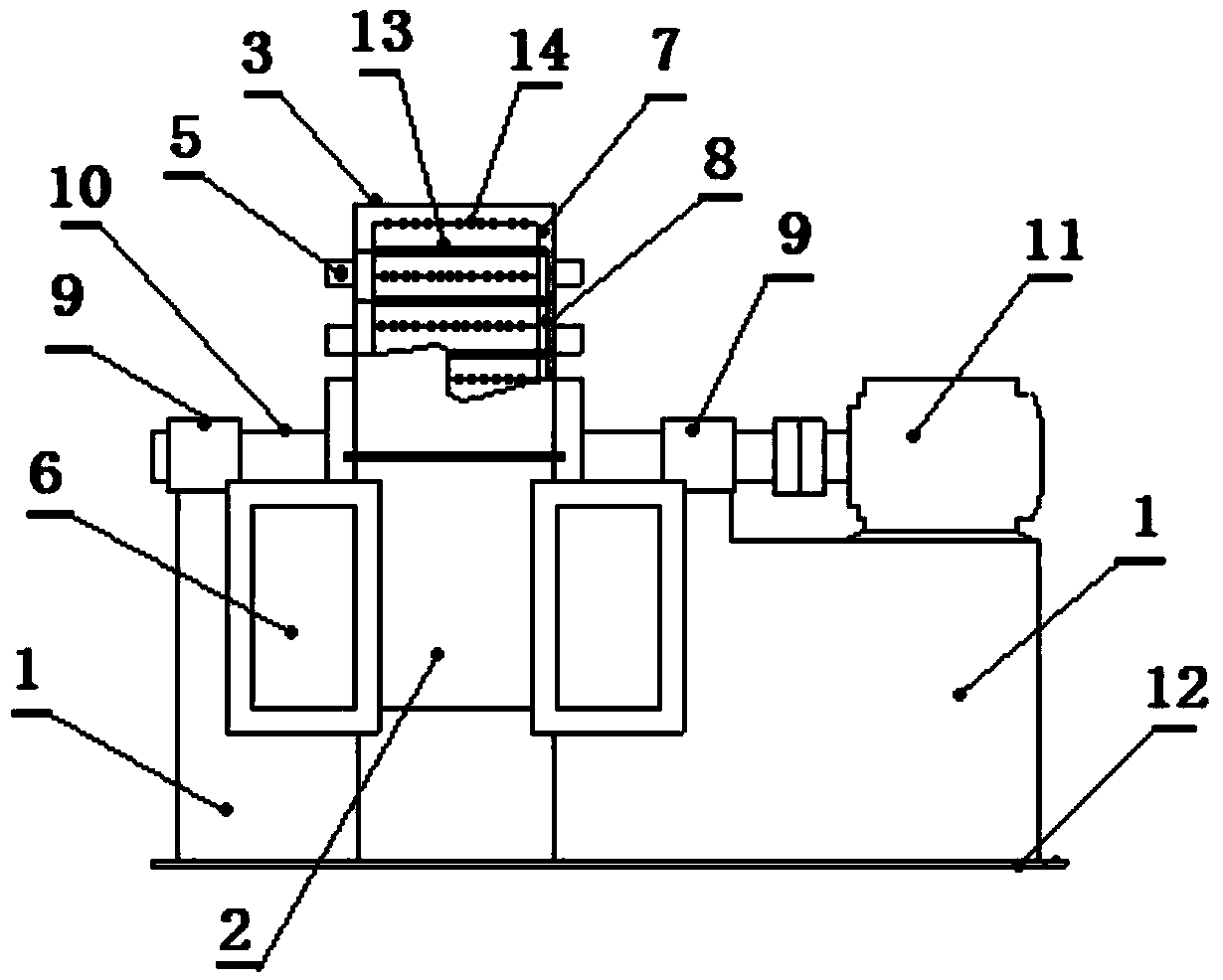
[0019] Such as figure 1 , figure 2 As shown, a dust waste gas treatment device is mainly composed of a support base 1, a lower casing 2, an upper casing 3, and a base 12. The support base 1 is arranged on the base 12, and the upper casing 3 is provided with an exhaust port 4. , the lower casing 2 is provided with an air inlet 6, the lower casing 2 and the upper casing 3 are semicircular cavities and are formed by welding a casing, the c...


PUM


Abstract

The invention discloses a dust and waste gas treatment device which mainly comprises a supporting seat, a lower housing, an upper housing and a base, wherein the supporting seat is arranged on the base; both the lower housing and the upper housing are semi-round cavities and are welded to form a housing; a motor arranged on the supporting seat is connected with a transmission shaft; the transmission shaft penetrates through the center of the housing and is arranged on the supporting seat through a fixing seat; rotary wheels and fixed rings are arranged in the housing; the rotary wheels are connected with the transmission shaft through a transmission device; the fixed rings are arranged on the housing; the rotary wheels and the fixed rings are radially arranged in a staggered manner; rotary blades and fixed blades are arranged on the axial rods of the rotary wheels and the fixed rings respectively; positions of solvent nozzles formed in the housing correspond to those of the rotary blades in the radial direction. According to the dust and waste gas treatment device, dust and waste gas are synchronously treated, equipment is compact, the occupied area is small, the daily operation and maintenance costs are low, the equipment is easy to operate, a process is easy to perform, the dust treatment efficiency can reach more than 99%, and the content of dust in discharged gas is less than 100 mg / m<3>.

Description

technical field [0001] The invention belongs to the technical field of environmental treatment, and in particular relates to a dust waste gas treatment device. Background technique [0002] In the production process of boiler flue gas, ferroalloy smelting, ore sintering, calcium carbide production and other industries, harmful exhaust gases such as sulfur dioxide, nitrogen oxides, and fluorine-containing gases are discharged, and a large amount of dust is discharged into the environment along with the exhaust gas, causing ambient air pollution. , with the improvement of national environmental protection standards and environmental protection requirements in recent years, in the above-mentioned polluting industries, no single exhaust gas or dust standard is used as the environmental protection standard requirement, but the dust and the generated waste gas must meet the corresponding standard requirements at the same time. To protect the environment, the dust emission requirem...

Claims


Application Information

Patent Timeline
Patent Type & Authority Applications(China)
IPC IPC(8): B01D47/06B01D53/18
CPCB01D47/06B01D53/78
Inventor 刘仁龙易德君崔良军王伟建
Owner ZUNYI TIANLI ENVIRONMENTAL ENG
Learn More