Solid electrolyte and secondary battery

A solid electrolyte and secondary battery technology, which is applied in the manufacture of secondary batteries, non-aqueous electrolyte batteries, and electrolyte batteries, and can solve the problems of high interface resistance and low battery performance.

Inactive Publication Date: 2015-01-07
TOYOTA IND CORP
View PDF10 Cites 26 Cited by
  • Summary
  • Abstract
  • Description
  • Claims
  • Application Information

AI Technical Summary

Problems solved by technology

However, the interface resistance between the solid electrolyte and the electrode material is high, and the battery performance is low

Method used


Image

  • Solid electrolyte and secondary battery
  • Solid electrolyte and secondary battery
  • Solid electrolyte and secondary battery

Examples


Embodiment 1

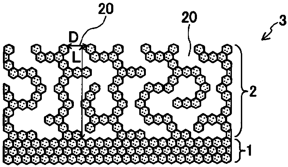
[0098] The solid electrolyte 3 of this example is as figure 1 As shown, it is composed of a dense part 1 and a porous part 2 formed on the surface side of a solid electrolyte 3 continuous with one surface of the dense part 1 . The dense part 1 has a planar shape. The sintered density of the dense part 1 was 98%. The open porosity of the dense part 1 is less than 1%. The thickness of the dense part 1 is about 50 μm. The ratio of the thickness of dense portion 1 to the entire thickness of solid electrolyte 3 was 25%.

[0099] The porosity of the porous portion 2 was 80%, and the open porosity of the porous portion 2 was 75%. The ratio of the open porosity of the porous portion 2 to the porosity of the porous portion 2 was 94%. The average opening diameter D of the open pores 20 opened on the surface of the porous portion 1 was 50 μm. The average depth L of the open pores 20 was 48 μm. The thickness of the porous portion 2 is about 100 μm. The ratio of the thickness of th...

Embodiment 2

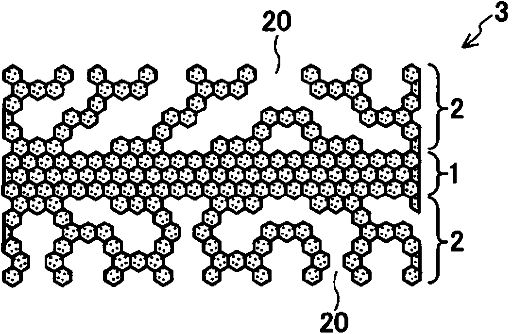
[0104] The solid electrolyte 3 of this example is as figure 2 As shown, the porous portion 2 is formed on both the front and back surfaces of the dense portion 1 . The thickness of the dense part 1 was 50 μm, and the thickness of each porous part 2 was 100 μm. The ratio of the thickness of dense portion 1 to the thickness of the solid electrolyte 3 as a whole was 20%. After the dense part 1 is formed, the solid electrolyte slurry is applied to both the front and back sides of the dense part 1, freeze-dried, and fired. Others are the same as in Example 1.

Embodiment 3

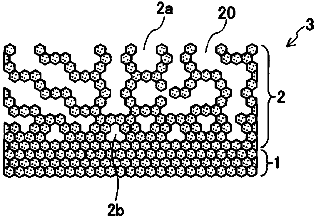
[0106] The solid electrolyte 3 of this example is as image 3 As shown, the porosity of the porous portion 2 has a gradient in the thickness direction. The porosity of the porous part 2 is 80% in the surface layer part 2a, and gradually decreases toward the inside, and the porosity is almost 0% in the inner part 2b near the dense part 1 in the porous part 2. When forming the porous part 2, with figure 1 Similarly, the solid electrolyte slurry was applied to the surface of the dense part 1, freeze-dried, and fired. The conditions for freeze-drying are to install a cooling medium on the top of the molded body and cool the molded body while imparting a temperature gradient. Others are the same as in Example 1.


PUM

PropertyMeasurementUnit
thicknessaaaaaaaaaa
thicknessaaaaaaaaaa
thicknessaaaaaaaaaa

Abstract

The purpose of the present invention is to provide a solid electrolyte which can prevent the penetration of dendrites of electrode components, and has high ion conductivity, and to provide a secondary battery using the electrolyte. A solid electrolyte according to the present invention is sheet-shaped, is formed from an oxide sintered body, and comprises: a layer-shaped compact section having a sintered density of 90% or more; and a porous section which is formed so as to connect with at least one surface of the compact section on the surface-side of the solid electrolyte, and which has a porosity of at least 50%. A secondary battery according to the present invention comprises the solid electrolyte, and a positive electrode and a negative electrode which are arranged at corresponding positions sandwiching the solid electrolyte. Also, a secondary battery according to the present invention comprises: a separator comprising solid electrolyte; the positive electrode and negative electrode which are arranged at corresponding positions sandwiching the separator; and electrolyte solution which is filled in the negative electrode-side where the negative electrode is disposed and/or the positive electrode-side where the positive electrode is disposed, sandwiching the separator.

Description

technical field [0001] The present invention relates to a solid electrolyte and a secondary battery using it. Background technique [0002] A lithium secondary battery using lithium metal as a negative electrode theoretically has a large battery capacity per unit mass and a high potential. In addition, no conductive additives and current collectors are required, and the cost of coating can be reduced with less coating work. [0003] However, when charge and discharge of the lithium secondary battery are repeated, lithium may grow in a tree shape to form a dendrite. The dendrites may penetrate through the separator and cause a short circuit, making the battery inoperable. Therefore, at present, most lithium ion secondary batteries use a carbon material for the negative electrode. Electrode components other than lithium may also grow dendrites due to repeated charging and discharging, but among them, lithium tends to grow dendrites. [0004] On the other hand, it is expect...

Claims


Application Information

Patent Timeline
Patent Type & Authority Applications(China)
IPC IPC(8): H01M10/0562H01B1/06H01M4/13H01M4/139H01M4/62H01M10/052H01M10/056H01M10/058
CPCH01M2300/0094Y02T10/7011H01M2300/0071H01M10/052C01G25/006C04B2235/606C04B35/486C01P2004/61Y02E60/122H01M10/0562C04B2235/3227C04B2235/3203C04B2235/764H01M4/13H01M4/366H01B1/08H01M4/134H01M4/382H01M4/62H01M10/058H01M4/131H01M4/525H01M4/386H01M4/387Y02E60/10Y02P70/50Y02T10/70
Inventor 渡边渚川澄一仁丹羽淳一仲西正孝
Owner TOYOTA IND CORP
Why Eureka
Try Eureka