Blocking structure for air heating furnace bottom air leakage

A realization method, a technology of a hot blast stove, applied in furnaces, blast furnaces, heating furnaces, etc.

Active Publication Date: 2015-01-21
CHINA MCC5 GROUP CORP
View PDF3 Cites 6 Cited by
  • Summary
  • Abstract
  • Description
  • Claims
  • Application Information

AI Technical Summary

Problems solved by technology

[0004] The purpose of the present invention is to provide a plugging structure and implementation method of air leakage at the bottom of the hot blast stove, to solve the problem of air leakage at the bottom of the current hot stove, and to achieve Realize the purpose of blocking without stopping production

Method used


Image

  • Blocking structure for air heating furnace bottom air leakage

Examples


Embodiment 1

[0033] A 1260m under construction in 2012 3 In the blast furnace project, during the trial operation, it was found that there was air leakage at the bottom of the three hot blast stoves, which would bring safety hazards to future production. The air leakage was calculated to be 1m 3 / min, the maximum temperature outside the furnace body is 55°C, and the working pressure of the furnace body is 0.3MP. In this regard, the company organized technical personnel to discuss the solution, and under the advice of relevant domestic technical experts, used high-grade cement mortar for secondary furnace bottom grouting Repair test, but the effect was not satisfactory; later, anhydrous phenolic resin repair technology developed by a famous domestic steel factory was used, but it failed because of poor material density, cracks in the material, or weak bonding between the sealing material and the metal body. Aiming at this specific working condition, after repeated research and experiments, ...

Embodiment 2

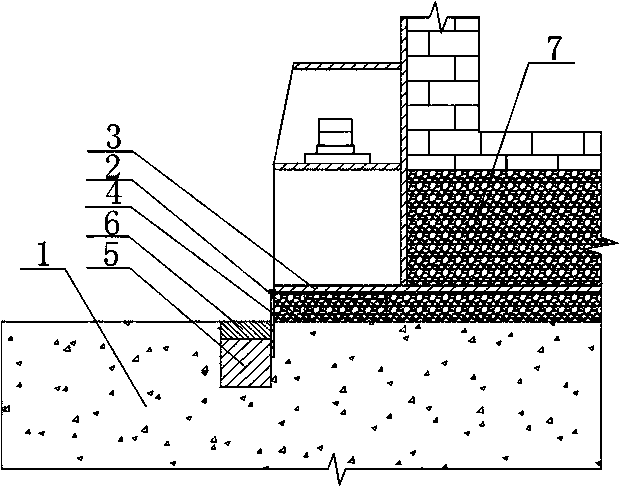
[0041] Such as figure 1 As shown, according to the structure obtained by the method of Example 1, the model of the groove is 80mm wide * 100mm, and the model of the steel plate 4 is 150mm wide * 10mm thick, and its length is equal to the 3 circumferences of the bottom of the hot blast stove. According to actual construction process, different models can be used, there is no need to stop production of the hot blast stove, and there is no need to operate the inner structure 7 of the hot blast stove. The gap enters the gap between the shim iron and the filling layer 2, and is sealed in the cavity formed by the steel plate 4, the concrete foundation 1, and the furnace bottom 3 of the hot blast stove. The gap between the steel plate 4 and the concrete foundation 1 can be realized by using a sealing material Sealing, the bonding between the bottom sealing layer 5 made of SHB planting glue and the steel plate 4 is very firm, the thickness of the bottom sealing layer 5 is 80mm, accor...


PUM

PropertyMeasurementUnit
thicknessaaaaaaaaaa
thicknessaaaaaaaaaa

Abstract

The invention discloses a blocking structure for air heating furnace bottom air leakage. The blocking structure comprises a concrete foundation. A sizing block and a packing layer are arranged on the concrete foundation, are provided with an air heating furnace bottom. A groove located in the outer side of the air heating furnace bottom edge is formed in the concrete foundation, a circle of steel plate is welded to the air heating furnace bottom edge, the lower end of the steel plate stretches into the groove, and the groove is filled with sealing materials. In the process of construction, sealing operation can be finished while production is carried out under the premise that a worker does not need to enter a furnace and the furnace does not need to be stopped. The production time of an air heating furnace is shortened, the time taken to maintain the air heating furnace and the machine-stopping time are shortened, and the purpose of sealing leaking portions in the process of producing is achieved.

Description

technical field [0001] The invention relates to an air leakage sealing structure of a hot blast stove, in particular to a sealing structure and a realization method for an air leakage at the bottom of a hot blast stove. Background technique [0002] Hot blast stoves began to be widely used in our country in the late 1970s. It has become a replacement product for electric heat sources and traditional steam power heat sources in many industries. Through long-term production practice, people have realized that only by using hot air as the medium and carrier can the heat utilization rate and thermal work effect be greatly improved. Traditional electric heat sources and steam thermal power are often equipped with multiple circulating fans during the transportation process, so that they will eventually form hot air indirectly for drying or heating operations. This process obviously has many shortcomings such as a large amount of waste of energy, excessive auxiliary equipment, and...

Claims


Application Information

Patent Timeline
Patent Type & Authority Applications(China)
IPC IPC(8): C21B9/10
Inventor 王青海胡云洁满胜文
Owner CHINA MCC5 GROUP CORP
Why Eureka
Try Eureka