
Single-core photonic crystal fiber polarization splitter

A technology of photonic crystal fiber and polarization beam splitter, which is applied in the direction of cladding fiber, optical waveguide, light guide, etc., can solve the problems of difficult production and complex structure, and achieve the effect of excellent crosstalk characteristics

Inactive Publication Date: 2015-01-21
TIANJIN UNIVERSITY OF TECHNOLOGY
View PDF1 Cites 8 Cited by
  • Summary
  • Abstract
  • Description
  • Claims
  • Application Information

AI Technical Summary

Problems solved by technology

The problems of the polarization beam splitters with the above two structures are: the structure is complex, the background material is quartz, and it is difficult to manufacture

Method used


Image

  • Single-core photonic crystal fiber polarization splitter
  • Single-core photonic crystal fiber polarization splitter
  • Single-core photonic crystal fiber polarization splitter

Examples


Embodiment

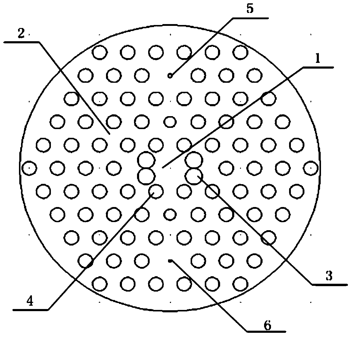
[0024] A photonic crystal fiber polarization beam splitter, such as figure 1 As shown, it is composed of core 1 and cladding 2, and the refractive index of cladding 2 is lower than that of core 1. The background material of cladding 2 is tellurate. There are four circular air holes a3 in the center and four circular The air holes b4 together form the core area, wherein the diameter of the circular air hole a3 is larger than the diameter of the circular air hole b4, the circular air holes a3 are arranged in two rows and the two circular holes in each row are tangent; the cladding 2 surrounds Fiber core 1, which is composed of circular air holes b4 with the same diameter and arranged periodically in a regular hexagon. There are five layers of circular air holes b4 periodically arranged, and two small circular air holes are arranged in the outer cladding c5 and the circular air hole d6 are located equidistantly and symmetrically with the fiber core 1 .

[0025] In this embodimen...


PUM


Abstract

A photonic crystal fiber polarization splitter is composed of a fiber core and a wrapping layer, wherein the refractive index of the wrapping layer is smaller than that of the fiber core, the background material of the wrapping layer is tellurate, four round air holes a and four round air holes b in the center of the wrapping layer jointly form a fiber core area, the round air holes a are arranged in two rows, the two round air holes a in each row are tangential, the fiber core is encircled by the wrapping layer, the wrapping layer is formed by round air holes b which have the same diameters and are arranged periodically in a regular hexagon mode, the total number of the layers of the round air holes b which are periodically arranged is five, and a small round air hole c and a small round air hole d are formed in the outer side of the wrapping layer and located at the positions symmetrical about the fiber core. The photonic crystal fiber polarization splitter has the advantages that zinc telluride serves as the background material of the polarization splitter, the polarization splitter is simple in structure, good in beam splitting effect and easy to manufacture; the small air holes are formed in the outer side of the wrapping layer to form defects, a defect mode is generated so that the defect mode is coupled to a fiber core mode, and the purpose that light is propagated in the orthogonal direction to be split is achieved.

Description

technical field [0001] The invention belongs to the technical field of optical fiber communication, in particular to a photonic crystal fiber polarization beam splitter. Background technique [0002] Photonic crystal fiber is a two-dimensional optical waveguide with defects, which is composed of quartz material with periodic microstructure air hole arrangement in the axial direction, and light transmission is realized through the confinement of light by tiny air holes. [0003] Compared with traditional optical fibers, photonic crystal fibers have incomparable characteristics: unlimited single-mode characteristics, high nonlinearity, high birefringence characteristics, adjustable dispersion characteristics, etc. [0004] Fiber Polarization Splitter (Fiber Polarization Splitter) is an important device in integrated optics. It can split a beam of light into two beams in orthogonal polarization states and transmit them in different directions. In the production of lasers, The...

Claims


Application Information

Patent Timeline
Patent Type & Authority Applications(China)
IPC IPC(8): G02B6/02
CPCG02B6/02357G02B6/02347
Inventor 曹晔赵舜童峥嵘
Owner TIANJIN UNIVERSITY OF TECHNOLOGY
Learn More