
Double resonance oscillation circular polarization and short back reflection C waveband antenna

A circularly polarized, short back-reflection technology, applied in the direction of antenna, antenna array, antenna grounding switch structure connection, etc., can solve the problems of antenna radiation and feeding and installation impact, inconvenient engineering application, etc., to achieve low sidelobe, antenna Simple structure and wide main lobe

Active Publication Date: 2015-01-28
XIAN AISHENG TECH GRP +1
View PDF4 Cites 4 Cited by
  • Summary
  • Abstract
  • Description
  • Claims
  • Application Information

AI Technical Summary

Problems solved by technology

However, in the literature, only the role of the parasitic element in the short backfiring antenna is discussed in principle, and the inclination angle of the inclined coupling line and the installation and fixing method are difficult to meet the simple, strong and durable engineering design requirements, and In its design, the method of installing and fixing the reflector through a support rod will affect the radiation, feeding and installation of the antenna, and it is not convenient for engineering applications

Method used


Image

  • Double resonance oscillation circular polarization and short back reflection C waveband antenna
  • Double resonance oscillation circular polarization and short back reflection C waveband antenna
  • Double resonance oscillation circular polarization and short back reflection C waveband antenna

Examples


Embodiment Construction

[0024] This embodiment is a dual-resonant circularly polarized short backfiring C-band antenna.

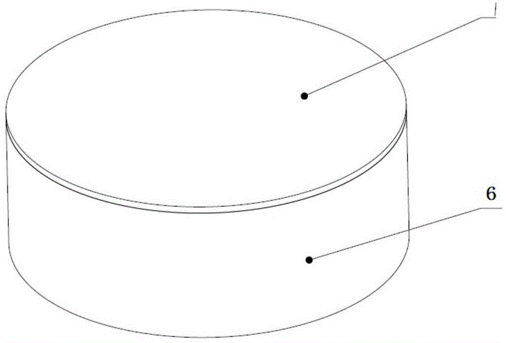
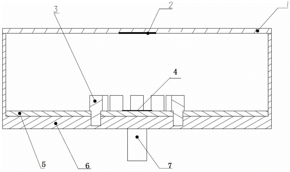
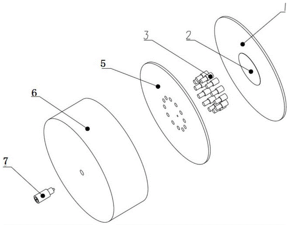
[0025] refer to Figure 1 to Figure 8 In this embodiment, the dual-resonant circularly polarized short backfiring C-band antenna consists of a reflector 1, a reflector 2, a parasitic element 3, a circularly polarized patch antenna array element 4, a circularly polarized patch antenna substrate 5, and a reflective cavity Body 6, RF connector 7. The reflective cavity 6 is a cylindrical structure with one end closed. The internal diameter of the reflective cavity 6 is 82 mm, the external diameter is 84 mm, and the height is 30 mm. The thickness of the bottom of the reflective cavity 6 is 4 mm. There are 12 threaded blind holes with a diameter of M3 and a depth of 3 mm; the reflective cavity 6 is processed and formed by aluminum alloy material, and the reflective cavity realizes the directional energy concentration and radiation effect of the antenna.

[0026] The circular polarizat...


PUM


Abstract

The invention discloses a double resonance oscillation circular polarization and short back reflection C waveband antenna. The double resonance oscillation circular polarization and short back reflection C waveband antenna uses a multifunctional spurious coupling array mode, and is characterized in that a reflection cavity is of a cylindrical structure with one end sealed, an antenna substrate is located at the bottom of the interior of the reflection cavity, an antenna array of a square corner cut shape is etched at the center of the antenna substrate, a plurality of spurious array pieces are evenly distributed along the circumference of the antenna array, the reflection cavity achieves an antenna pointing energy convergence radiation function, the spurious array pieces achieve electromagnetic coupling, fixation support and antenna substrate positioning functions, a reflection plate is fixedly connected with an open end of the reflection cavity, a round reflector piece is pasted at the center of the reflection plate, the reflection plate is parallel and opposite to the antenna array, a radio frequency connection piece is located at the center of the outer end of the reflection cavity, one end of the radio frequency connection piece is fixedly connected with a cable, and the other end of the radio frequency connection piece passes through the reflection cavity and is connected with the antenna array. The double resonance oscillation circular polarization and short back reflection C waveband antenna is simple in structure, has the advantages of being wide in main lobe, low in side lobe, portable and small, and is suitable for satellite communications, navigation communications and ground anti-interference communications.

Description

technical field [0001] The invention belongs to the technical field of radar antennas, and in particular relates to a dual-resonant circularly polarized short back-firing C-band antenna. Background technique [0002] At present, the front-end antennas of star-to-satellite data communication transmission and ground anti-jamming communication systems are mostly in the form of circularly polarized antennas, such as helical radiation antennas and Archimedes helical antennas. These antennas often have relatively large antenna size, complicated antenna feed system matching, and relatively high antenna processing costs. In the field of mobile communications such as airborne and high-speed trains, as well as in high-precision direction-finding systems, in order to extend the communication distance and suppress the multipath interference of ground communications, it must also meet the characteristics of miniaturization, easy production and installation; the new circular polarization ...

Claims


Application Information

Patent Timeline
IPC IPC(8): H01Q1/36H01Q1/38H01Q1/50H01Q19/18H01Q21/00
Inventor 刘亚成戚勇张朋彭飞
Owner XIAN AISHENG TECH GRP
Learn More