High-numerical-aperture optical fiber point diffraction interference device used for three-coordinate measurement and method thereof

A three-coordinate measurement and point diffraction interference technology, which is applied in the field of large numerical aperture optical fiber point diffraction interference devices, can solve the problems of complex production, limited measurement range, low convergence area and easy divergence, etc., and meet the requirements of reducing photosensitivity and expanding measurement Range, Simplify Effects of Adjusting Difficulty

Active Publication Date: 2015-02-04
CHINA JILIANG UNIV
View PDF6 Cites 19 Cited by
  • Summary
  • Abstract
  • Description
  • Claims
  • Application Information

AI Technical Summary

Problems solved by technology

The three-coordinate measuring machine needs to be configured with complicated and expensive long guide rails and a huge measuring platform. Its structure is complicated and the equipment is huge.
The structure is based on a single-mode optical fiber to obtain a point-diffraction spherical wavefront with high brightness, which solves the problems of complex structure, huge equipment and the need to configure precision guide rails in traditional three-...

Method used


Image

  • High-numerical-aperture optical fiber point diffraction interference device used for three-coordinate measurement and method thereof
  • High-numerical-aperture optical fiber point diffraction interference device used for three-coordinate measurement and method thereof
  • High-numerical-aperture optical fiber point diffraction interference device used for three-coordinate measurement and method thereof

Examples


Embodiment 1

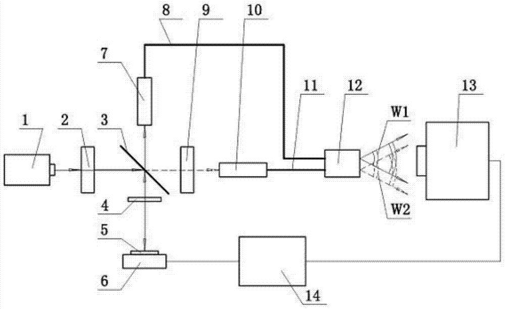
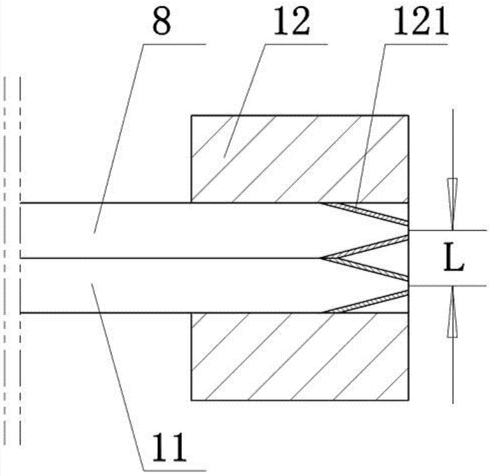
[0017] like figure 1 and 2 As shown, a large numerical aperture fiber point diffraction interference device for three-coordinate measurement, which includes a laser 1, a half-wave plate I2, a polarization beam splitting prism 3, a quarter-wave plate 4, a mirror 5, Phase shifter 6, fiber coupler I7, subwavelength aperture single-mode fiber I8, half-wave plate II9, fiber coupler II10, subwavelength aperture single-mode fiber II11, measuring probe 12, CCD detector 13, computer 14 . figure 1 Thin lines with arrows in the middle represent light, and thin lines without arrows represent circuit connections. Laser 1 is a He-Ne polarized laser. The direction of the fast axis of the quarter-wave plate 4 forms an included angle of 45° with the x-axis. The phase shifter 6 is a piezoelectric ceramic phase shifter with high displacement resolution and high frequency response. The mirror 5 is connected to the end face of the phase shifter 6 . The number of pixels of the CCD detector 13...


PUM

PropertyMeasurementUnit
Diameteraaaaaaaaaa
Thicknessaaaaaaaaaa

Abstract

The invention provides a high-numerical-aperture optical fiber point diffraction interference device used for three-coordinate measurement and a method thereof, and relates to optical measurement. Light emitted by a laser device is divided into transmission light and reflected light via a polarized beam splitting prism. Point diffraction spherical wave front W2 is generated at a sub-wavelength aperture optical fiber emergent end by transmission light, and point diffraction spherical wave front W1 is generated at the sub-wavelength aperture optical fiber emergent end by reflected light after being reflected by a moving reflecting mirror. A CCD detector acquires W1 and W2 interference fringes, and three-dimensional coordinate measurement of a measured object is realized via multi-step phase-shifting and a double iteration algorithm of an L-M algorithm. A problem in the prior art that high-numerical-aperture and high-energy diffraction spherical wave front is difficult to realize simultaneously by a point diffraction interferometer used for three-coordinate measurement is solved. The beneficial effects are that probes of two sub-wavelength aperture optical fibers act as measuring probe heads, the high-brightness and high-numerical-aperture point diffraction spherical wave front is acquired, the requirement of light sensitivity is reduced and measurement range of an optical fiber point diffraction interference system used for three-coordinate measurement is enlarged.

Description

technical field [0001] The invention relates to the technical field of optical measurement, in particular to a large numerical aperture optical fiber point diffraction interference device and a measurement method for three-coordinate measurement. Background technique [0002] With the development of modern precision measurement technology, 3D coordinate measurement technology has gained more and more attention in various fields of precision measurement, design and production and processing, such as spatial positioning, large workpiece assembly, dimension measurement, mold design, manufacture and inspection, automobile manufacturing, etc. wider application. At the same time, with the continuous development of precision machining and manufacturing technology, the demand for three-dimensional coordinate measurement technology is also increasing. At present, three-dimensional coordinate measurement mainly adopts three-coordinate measuring machine and multi-channel laser tracker...

Claims


Application Information

Patent Timeline
IPC IPC(8): G01B11/03
Inventor 王道档陈茜茜徐杨波刘维赵军孔明
Owner CHINA JILIANG UNIV
Why Eureka
Try Eureka