Hydropower station set vibration measurement monitoring method

A technology of vibration measurement and hydropower station, which is applied in the direction of measuring devices, measuring ultrasonic/sonic/infrasonic waves, using electrical devices, etc., can solve the problems of unreliable measurement signals, measurement errors, failure of compensation circuits, and short service life of sensors, so as to solve the problems of measurement Effects of signal distortion or failure, small lateral interference, and high sensitivity

Inactive Publication Date: 2015-02-04
白山发电厂 +2
View PDF0 Cites 7 Cited by
  • Summary
  • Abstract
  • Description
  • Claims
  • Application Information

AI Technical Summary

Problems solved by technology

[0006] Since this type of sensor is equipped with movable mechanical devices such as inertial mass, coil and spring damping, it is extremely prone to mechanical fatigue and jamming during long-term operation , resulting in measurement failure and short sensor life
[0007]2. Measurement error and compensation circuit failure caused by seismic geophone resonance
[0009] (1) There are a large number of vibration signals between 10Hz and 30Hz in the real vibration of the hydroelectric generating set, which may easily cause the resonance of the geophone, resulting in inaccurate measurement. precise
[0010] (2) Under certain operating conditions of the hydroelectric generating set, the fluid impacts the frame and the top cover, which will cause the detector to Resonance; when the detector resonates, the output of the sensor not only cannot guarantee the accuracy of the measurement, but also introduces a vibration signal of a false frequency. At the same time, the resonance signal is amplified by the frequency end compensation circuit of the sensor, which is extremely easy to cause the circuit to fail. , causing unreliable measurement signals
[0012]The above reasons are the reasons why there are a large number of signal failures and poor stability in the field use of magnetoelectric inertial low-frequency vibration sensors
Therefore, this type of sensor cannot be used in online monitoring and vibration swing protection systems that require high reliability

Method used


Image

  • Hydropower station set vibration measurement monitoring method

Examples


Embodiment Construction

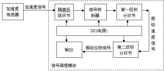
[0032] see figure 1 , The vibration measurement and monitoring method of the hydropower unit includes: a piezoelectric acceleration sensor, a pre-processing module, a protection data acquisition device to complete A / D data acquisition, and is responsible for suppressing the resonance signal of the sensor; the piezoelectric acceleration sensor and the pre-processing module Low-noise, low-attenuation cables are used to ensure that electrical signals do not bring attenuation and greater noise during transmission.

[0033] Function description of each link of the signal conditioning module:

[0034] DC blocking low resistance link: operational amplifier. This is a high-pass filter link, the corner frequency is designed at 0.5Hz to remove the DC signal component output by the acceleration sensor and the interference noise signal below 0.5Hz.

[0035] The first and second integration links: operational amplifiers. This is an integration link with a suppressor and a corrector, wh...


PUM


Abstract

The invention relates to the hydropower station set detection field, and particularly relates to a hydropower station set vibration measurement monitoring method. A piezoelectric acceleration sensor and a pre processing module are provided. A protection data acquisition device finishes A/D data acquisition and is in charge of suppressing sensor resonance signals at the same time; and a low-noise and low-attenuation cable is adopted between the piezoelectric acceleration sensor and the pre processing module, so as to ensure electric signals not to bring attenuation and larger noise in the transmission process. When the piezoelectric acceleration sensor is applied to hydropower station set vibration measurement, features of high sensitivity, low noise, low frequency response and the like are provided, voltage signals outputted by low-frequency small-amplitude vibration signals can be ensured to be strong enough, true low-frequency small-amplitude acceleration signals can be ensured not to be overwhelmed by the noise signals, vibration signals as low as 0.5Hz can be detected, and problems of distortion, or failure, poor precision and the like of the original inertial low-frequency vibration sensor measurement signals are solved.

Description

[0001] technical field [0002] The invention relates to the detection field of a hydropower station unit, namely a method for measuring and monitoring the vibration of a hydropower station unit. Background technique [0003] In the prior art, at present, the magnetoelectric (moving coil) inertial low-frequency vibration sensor is mainly used in the field of structural vibration measurement of domestic conventional hydroelectric generating units. The minimum response frequency of the sensor can reach about 0.5Hz, and the maximum response frequency can reach more than 200Hz. It is widely used in the absolute vibration displacement measurement of the frame, top cover and other positions of the hydroelectric generating set. This type of sensor can obtain the lowest frequency signal of 0.5Hz at the frame and top cover, but due to design principle problems, its reliability and stability in long-term use have been difficult to solve, and measurement signal distortion or failure, poo...

Claims


Application Information

Patent Timeline
Patent Type & Authority Applications(China)
IPC IPC(8): G01H11/08
Inventor 张策乔木栾春林胡海平潘月国刘淑娟张德浩刘福佳
Owner 白山发电厂
Why Eureka
Try Eureka