A kind of power cable with drying layer

A technology of power cable and drying layer, applied in the field of power cable with drying layer, can solve the problems of easily damaged cable core, no drying layer, high interference humidity, etc., and achieves stable performance, which is not easy to fall off, prevents the intrusion of water vapor Effect

Active Publication Date: 2016-09-14
STATE GRID CORP OF CHINA +2
View PDF8 Cites 0 Cited by
  • Summary
  • Abstract
  • Description
  • Claims
  • Application Information

AI Technical Summary

Problems solved by technology

[0003] Power cables are generally used outdoors or buried underground. The surrounding environment is generally harsh, and there is a lot of water vapor around us. Some power cables are set in special locations, and the surrounding interference humidity will be relatively large. Even buried in the seabed, etc., such a long time in a high-humidity environment will inevitably cause great damage to the cable itself. Moreover, the power cable has strong radiation, which will also cause harm to people who are close to the power cable. great influence
However, the cables in the prior art are only equipped with copper mesh or steel wires inside to ensure the transmission of signals, and there is no drying layer, so that water vapor is very easy to damage the cable core; so these problems need to be solved urgently

Method used


Image

  • A kind of power cable with drying layer
  • A kind of power cable with drying layer
  • A kind of power cable with drying layer

Examples


Embodiment 1

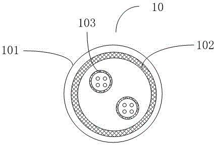
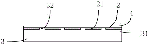
[0020] Such as figure 1 As shown, a power cable with a dry layer, the power cable 10 includes a cable shell 101 and a cable core 103, the power cable 10 also includes a dry layer structure 102, the dry layer structure 102 is arranged on the inner surface of the cable shell 101, as figure 2 , 3 As shown, wherein the dry layer structure 102 includes a flexible substrate 3, a polymer layer 31 and a dry layer 21, the dry layer 21 is embedded on the side of the surface of the polymer layer 31 away from the flexible substrate 3, the dry layer 21 is formed by the arrangement of drying blocks 2 arrays, and the drying blocks 2 are composed of desiccant; the distance between the adjacent drying blocks 2 is 150 μm to 300 μm, and the adjacent drying blocks 21 are mutually Independence; the present invention provides a power cable with a dry layer. The structure adopts a dry layer between the cable core and the cable sheath, which can well prevent the intrusion of water vapor and protect...

Embodiment 2

[0024] Such as figure 2 , 3 As shown, wherein the dry layer structure 102 includes a flexible substrate 3, a polymer layer 31 and a dry layer 21, the dry layer 21 is embedded on the side of the surface of the polymer layer 31 away from the flexible substrate 3, the dry layer 21 is formed by the arrangement of drying blocks 2 arrays, and the drying blocks 2 are made of desiccant; the desiccant is composed of bentonite, attapulgite, silica gel, calcium chloride, magnesium sulfate, calcium sulfate, silicon dioxide and poly Acrylamide composition.

[0025] Among them, take two containers respectively, take bentonite: 50 parts, 55 parts, attapulgite: 20 parts, 27 parts, silica gel: 22 parts, 25 parts, calcium chloride: 15 parts, 20 parts, respectively put into two In the container, put magnesium sulfate: 8 parts, calcium sulfate: 12 parts, silicon dioxide: 18 parts, polyacrylamide: 3 parts, put them into two containers respectively, and then configure them into ink, using silk s...

Embodiment 3

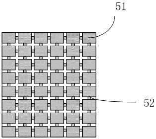
[0027] In another preferred solution, the drying layer structure 102 can also be a continuous structure, the drying layer structure 102 includes drying pieces 51 and connecting pieces 52, the drying pieces 51 are arranged in an array, and the adjacent drying pieces 51 Connect by connecting piece 52, form an integral dry layer; Wherein, be filled with mixed material in the dry piece 51; Said mixed material is made of aluminum, nickel, chromium, bentonite, attapulgite, silica gel, calcium chloride, magnesium sulfate, Calcium sulfate, silicon dioxide and polyacrylamide.

[0028] Among them, aluminum: 30 parts, nickel: 10 parts, chromium: 10 parts, bentonite: 60 parts, attapulgite: 35 parts, silica gel: 25 parts, calcium chloride: 20 parts, magnesium sulfate: 8 parts, sulfuric acid Calcium: 12 parts, silicon dioxide: 18 parts, polyacrylamide: 3 parts; put it into a container, then configure it into ink, and use screen printing to form the mixed material on the substrate; In this ...


PUM


Abstract

The invention provides a power cable with a metal mesh structure. The power cable comprises a cable shell and a cable core. The power cable also comprises the metal mesh structure which is arranged at the internal surface of the cable shell. The metal mesh structure comprises a flexible substrate and a metal mesh which is arranged at the surface of the flexible substrate. The metal mesh is composed of a first metal mesh line and a second metal mesh line which are intersected with each other, and the first metal mesh line and the second metal mesh line are made of conductive material. One side provided with the metal mesh structure orients towards the cable shell. According to the power cable with the metal mesh structure, the metal mesh is applied to be adhered on the flexible substrate, and one side provided with the metal mesh orients towards the outside so as to be well insulated from the cable core and great in inflexibility, and relatively disordered metal wires do not occur in cutting. Besides, metal material enhancing rigidity and adhesive force of the metal mesh structure is additionally arranged in metal material so that stability of the metal mesh structure is enhanced.

Description

technical field [0001] The invention relates to the technical field of power cables, in particular to a power cable with a dry layer. Background technique [0002] Power cable (power cable), a cable used to transmit and distribute electrical energy. It is often used in urban underground power grids, outgoing lines of power stations, internal power supply of industrial and mining enterprises, and underwater transmission lines across rivers and seas. In power lines, the proportion of cables is gradually increasing. Power cables are cable products used to transmit and distribute high-power electric energy in the main line of the power system, including 1-500KV and above various voltage levels and various insulated power cables. [0003] Power cables are generally used outdoors or buried underground. The surrounding environment is generally harsh, and there is a lot of water vapor around us. Some power cables are set in special locations, and the surrounding interference humid...

Claims


Application Information

Patent Timeline
Patent Type & Authority Patents(China)
IPC IPC(8): H01B7/28H01B7/29H01B9/02
CPCY02A30/14
Inventor 朱伟张杰付聪陈万田郑永文郑海山
Owner STATE GRID CORP OF CHINA
Why Eureka
Try Eureka