Spiral tap
A technology of spiral taps and taps, applied in thread cutting tools, drilling/drilling equipment, drilling tool accessories, etc., can solve the problems of poor positioning effect, low processing hole precision, low processing efficiency, etc., to avoid repeated processing , reduce production costs, and have a strong ability to withstand pressure
- Summary
- Abstract
- Description
- Claims
- Application Information
AI Technical Summary
Problems solved by technology
Method used
Image

Examples
Embodiment 1
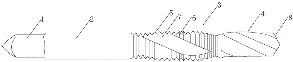
[0017] see Figure 1-Figure 4 As shown, the spiral tap includes a clamping portion 1, a handle 2 connected to the clamping portion, and a cutter head 3 connected to the handle; the front end of the clamping portion is conical, and the conical clamping portion has a Positioning function, and the clamping part is solid, its ability to withstand pressure is strong, which can effectively avoid the cracking of the clamping part, so that the service life of the spiral tap is longer; the cutter head includes the drilling part of the second half 4, and the tap part 5 of the first half; the tap part circumferential surface is uniformly distributed with tapping blades 6 in the axial direction, and can be drilled through the drilling part of the second half of the cutter head, and through the tap part of the cutter head Uniformly distributed tapping blades for tapping, so as to ensure drilling and tapping at the same time, avoid repeated processing, and reduce production costs; the tap p...
Embodiment 2
[0019] On the basis of the foregoing embodiment 1, the clamping part and the knife handle are integrally formed, and both are made of No. 45 steel; the knife handle is welded to the cutter head, and the cutter head is made of hard alloy. Because the cutter head is made of hard alloy, the hard alloy has strong wear resistance and heat resistance, thereby ensuring the wear resistance and heat resistance of the cutter head; while the clamping part and handle are made of 45 steel, because the cost of 45 steel is low, Thereby reducing the production cost of the spiral tap.
Embodiment 3
[0021] On the basis of the foregoing embodiment 1, the outer surface of the cutter head is coated with three layers of coatings, which are titanium alloy layer inner coating 9, titanium nitride layer 10 and aluminum nitride titanium outer coating 11 from the inside to the outside. . Three kinds of coatings are coated on the outer surface of the cutter head so that the outer surface of the cutter head has the characteristics of high hardness, good toughness, good wear resistance, stable chemical properties, heat resistance and oxidation resistance, and small friction coefficient, especially in ultra-high cutting It can exhibit excellent performance in hard and other difficult-to-machine materials.
PUM
 Abstract
Description
Claims
Application Information