Supercharge Your Innovation With Domain-Expert AI Agents!

Preheating device for chemical vapor deposition furnace

A chemical vapor deposition, preheating device technology, applied in gaseous chemical plating, metal material coating process, coating and other directions, can solve the problem of increasing the heat radiation capacity of the gas heating time, increasing the height of the preheating device, and the height of product charging. Reduce and other problems to achieve the effect of prolonging the residence time, increasing the charging height, and increasing the heat radiation area

Inactive Publication Date: 2015-02-18
XIAN AVIATION BRAKE TECH
View PDF2 Cites 15 Cited by
  • Summary
  • Abstract
  • Description
  • Claims
  • Application Information

AI Technical Summary

Problems solved by technology

At the same time, each layer of preheating partitions has beams, and they are placed alternately at 180°, which increases the heat radiation capacity and gas heating time to a certain extent. However, when the gas flow rate is large, it is still necessary to increase the number of layers of preheating partitions To ensure the preheating effect of the gas, the height of the preheating device is increased, the height of the product is reduced, and the utilization rate of the equipment is reduced.

Method used


Image

  • Preheating device for chemical vapor deposition furnace
  • Preheating device for chemical vapor deposition furnace
  • Preheating device for chemical vapor deposition furnace

Examples


Embodiment Construction

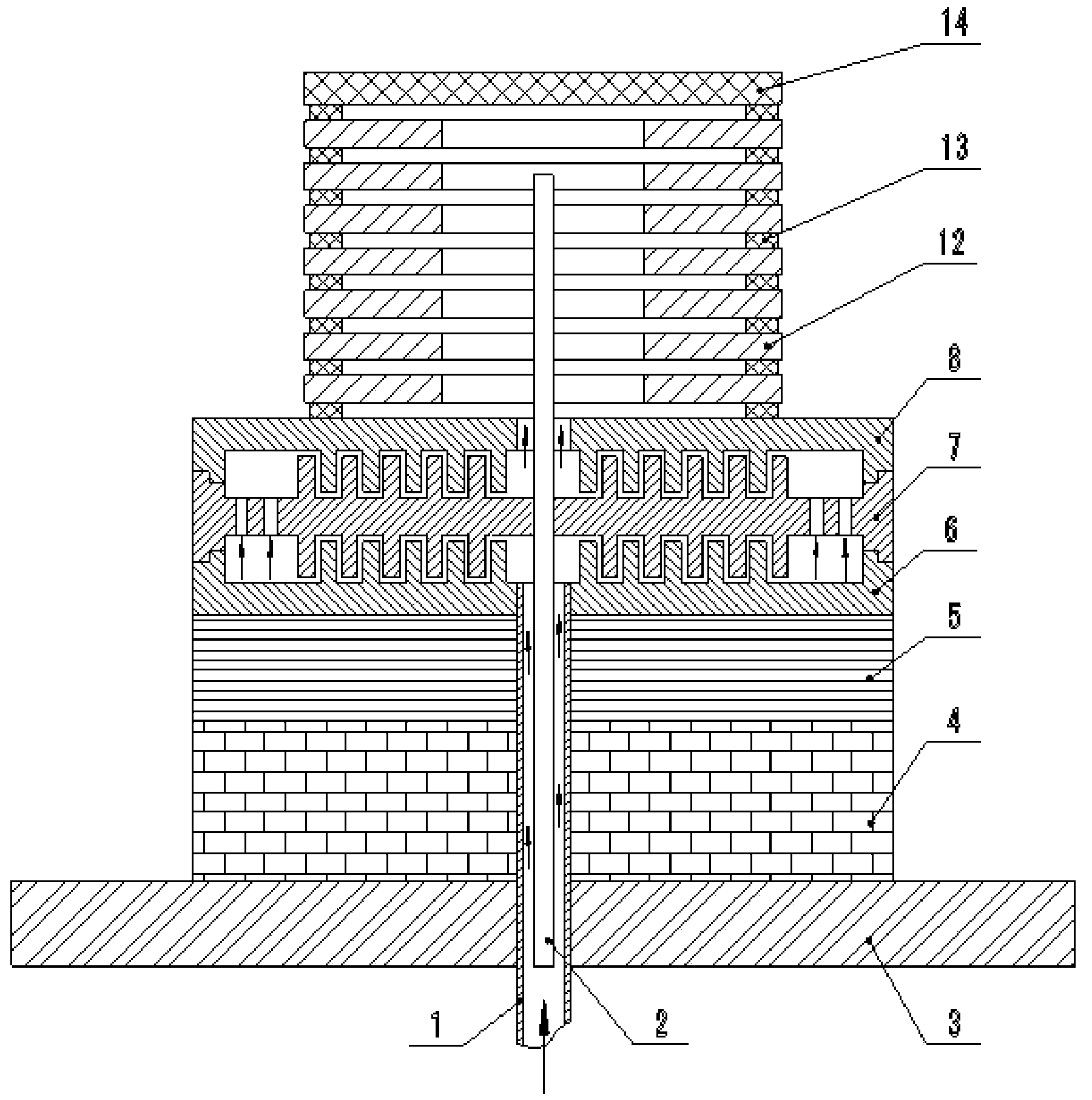
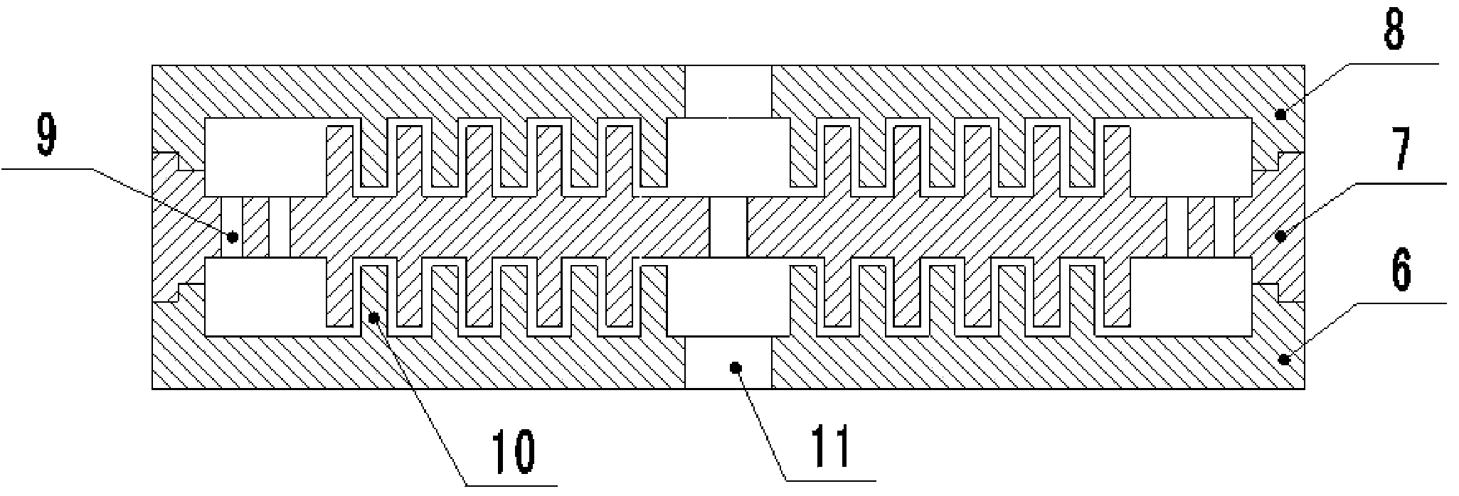
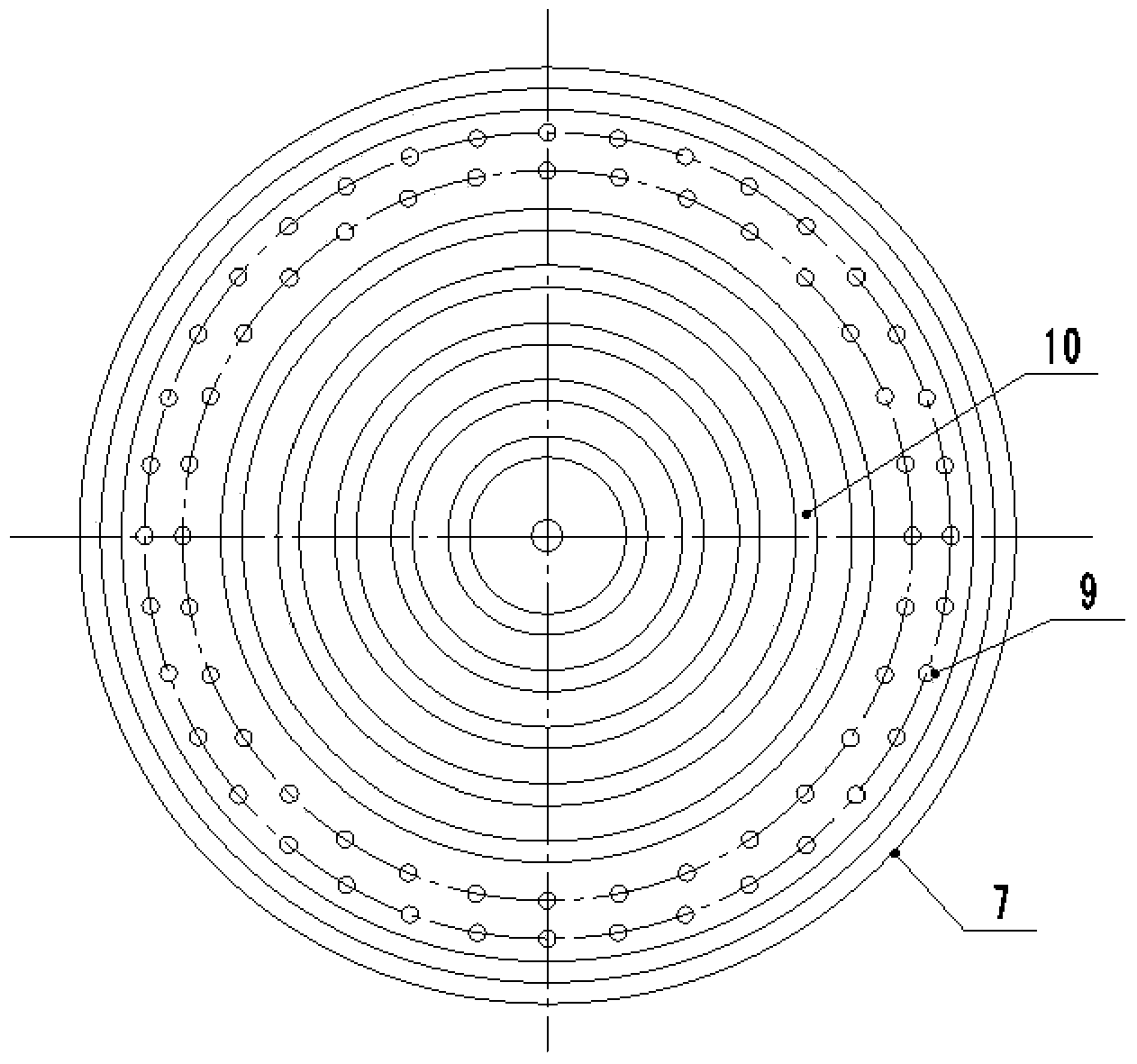
[0021] This embodiment is a chemical vapor deposition furnace preheating device, including a chemical vapor deposition furnace base and a preheating device, wherein the chemical vapor deposition furnace base is composed of a base bottom plate 3 , refractory bricks 4 , and insulation felt 5 . The preheating device is placed on the thermal insulation felt 5, the carbon fiber prefabricated body 12 is stacked on the surface of the preheating device, the carbon fiber prefabricated bodies 12 are separated by graphite gasket rings 13, and the graphite cover plate 14 is placed on the carbon fiber prefabricated body 12 material column the top of. The air intake pipe 1 is placed in the central hole of the base, and the end of the air intake pipe 1 communicates with the bottom end of the preheating device. The lower end of the thermocouple 2 is located in the intake pipe 1, and the upper end passes through the center of the preheating device and extends to the inside of the carbon fiber ...


PUM


Abstract

The invention relates to a preheating device for a chemical vapor deposition furnace. The preheating device consists of a preheating bottom plate, a preheating baffle and a preheating cover plate, which have the same outer diameters and are successively stacked from bottom to top. Support stairs which are respectively protruded from surfaces are arranged on the peripheries of the inner surface of the preheating bottom plate, the upper surface and the lower surface of the preheating baffle, and the inner surface of the preheating cover plate. Coaxial annular bosses of the same number are respectively processed on the inner surface of the preheating bottom plate, the upper surface and the lower surface of the preheating baffle, and the inner surface of the preheating cover plate. Two circles of air current holes are annularly and uniformly distributed between the support stairs on the preheating baffle and the outermost annular boss. According to the invention, the annular bosses are mutually crossed and meshed to form an air flow path, so that the heat radiation area and the air circulation path in the preheating device are effectively increased, the linear diffusion, in the prior art, of the air is changed into the Z-shaped diffusion, the residence time of the air in the preheating device is further prolonged, the preheating efficiency of the preheating device is improved, and the air can be sufficiently preheated before entering a reaction zone.

Description

technical field [0001] The invention relates to the technical field of chemical vapor deposition, in particular to a preheating device for a chemical vapor deposition furnace. Background technique [0002] The preparation of carbon / carbon composite materials by chemical vapor deposition method is to pass the reaction gas into the deposition furnace, enter the reaction zone after preheating, penetrate into the carbon fiber prefabricated body by diffusion, convection, etc. for cracking and polymerization, and finally heat The decarbonized form is deposited on the surface and pores of carbon fibers to achieve the effect of densification. A key factor affecting the densification efficiency is the preheating effect of the gas before entering the reaction zone. Therefore, how to reasonably optimize the structure of the gas preheating device is particularly important. [0003] At present, the preheating device of the chemical vapor deposition furnace generally adopts the superimpo...

Claims


Application Information

Patent Timeline
IPC IPC(8): C23C16/26C23C16/455
CPCC23C16/26C23C16/455
Inventor 施伟伟卢钢认刘海平
Owner XIAN AVIATION BRAKE TECH
Features
  • R&D
  • Intellectual Property
  • Life Sciences
  • Materials
  • Tech Scout
  • Unparalleled Data Quality
  • Higher Quality Content
  • 60% Fewer Hallucinations
Learn More