Device and method for testing electric strength of dielectric fluid under inhomogeneous field
A technology of non-uniform field and electric strength, applied in the direction of testing dielectric strength, etc., can solve the problem of not finding non-uniform electric field liquid and so on
- Summary
- Abstract
- Description
- Claims
- Application Information
AI Technical Summary
Problems solved by technology
Method used
Image
Examples
specific Embodiment approach 1
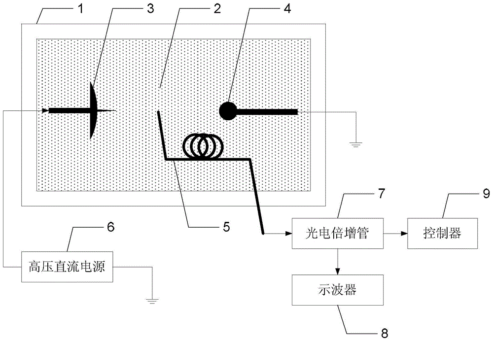
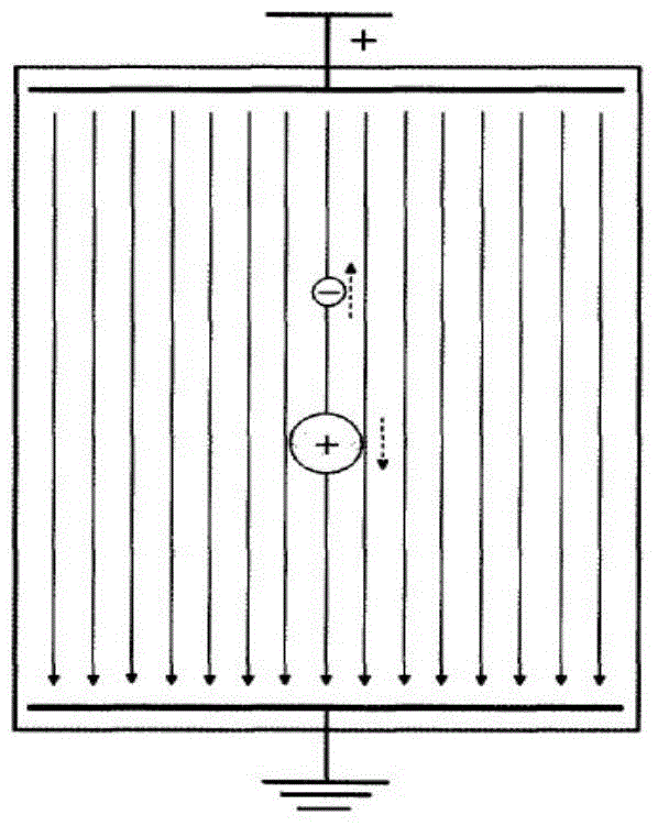
[0018] Specific implementation mode one: the following combination figure 1 and figure 2 Describe the present embodiment, the test device for the dielectric strength of the liquid dielectric under the non-uniform field described in the present embodiment, which includes a reaction vessel 1, the interior of the reaction vessel 1 is filled with a liquid dielectric 2, and the interior of the reaction vessel 1 is relatively provided with a needle-type high voltage Electrode 3 and ground electrode 4, the optical input end of optical fiber 5 is arranged at the gap between the discharge end of needle-type high-voltage electrode 3 and the arc receiving end of ground electrode 4, and the optical output end of optical fiber 5 is connected to the optical signal input end of photomultiplier tube 7 , the electrical signal output end of the photomultiplier tube 7 is connected to the display signal input end of the oscilloscope 8; the electrical signal output end of the photomultiplier tube...
specific Embodiment approach 2
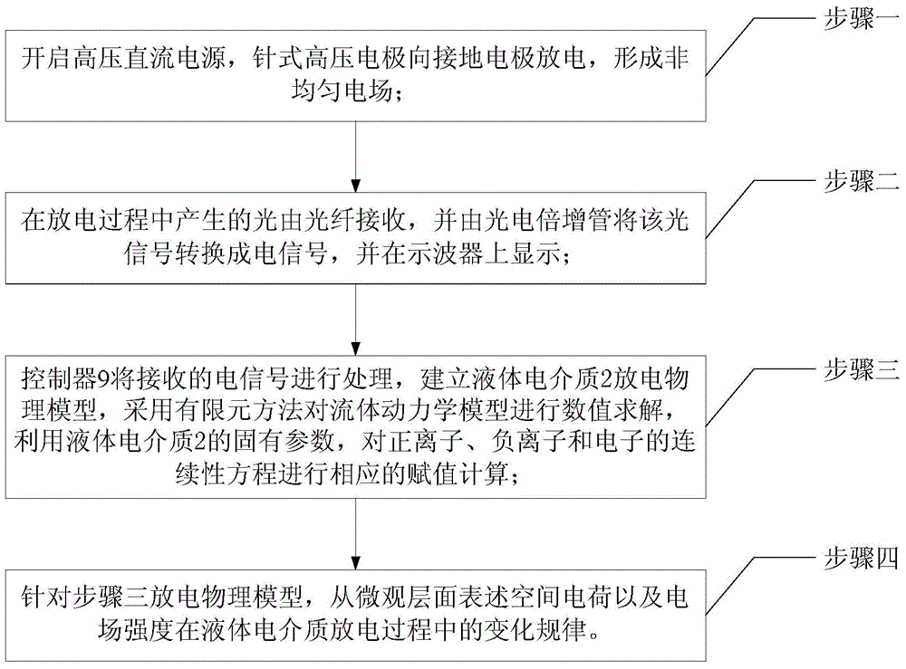
[0025] Specific implementation mode two: the following combination image 3 To illustrate this embodiment, according to the method of the test device for the dielectric strength of a liquid dielectric under a non-uniform field described in Embodiment 1, the method includes the following steps:
[0026] Step 1: Turn on the high-voltage DC power supply 6, and the needle-type high-voltage electrode 3 discharges to the ground electrode 4 to form a non-uniform electric field;
[0027] Step 2, the light generated during the discharge process is received by the optical fiber 5, and the optical signal is converted into an electrical signal by the photomultiplier tube 7, and displayed on the oscilloscope 8;
[0028] Step 3, the controller 9 processes the received electrical signal, establishes a physical discharge model of the liquid dielectric 2, uses the finite element method to numerically solve the fluid dynamics model, and utilizes the inherent parameters of the liquid dielectric ...
PUM
 Abstract
Description
Claims
Application Information
 - R&D
- Intellectual Property
- Life Sciences
- Materials
- Tech Scout
- Unparalleled Data Quality
- Higher Quality Content
- 60% Fewer Hallucinations
Browse by: Latest US Patents, China's latest patents, Technical Efficacy Thesaurus, Application Domain, Technology Topic, Popular Technical Reports.
© 2025 PatSnap. All rights reserved.Legal|Privacy policy|Modern Slavery Act Transparency Statement|Sitemap|About US| Contact US: help@patsnap.com


