
Micro-electromechanical systems (MEMS) device assembling technology

A process and device technology, applied in the field of MEMS device integration process, can solve the problems of reducing the performance and yield of fabricated devices, device failure, increasing power consumption, etc., to save device packaging volume, reduce failure probability, and improve yield. Effect

Active Publication Date: 2015-02-25
WUHAN XINXIN SEMICON MFG CO LTD
View PDF5 Cites 3 Cited by
  • Summary
  • Abstract
  • Description
  • Claims
  • Application Information

AI Technical Summary

Problems solved by technology

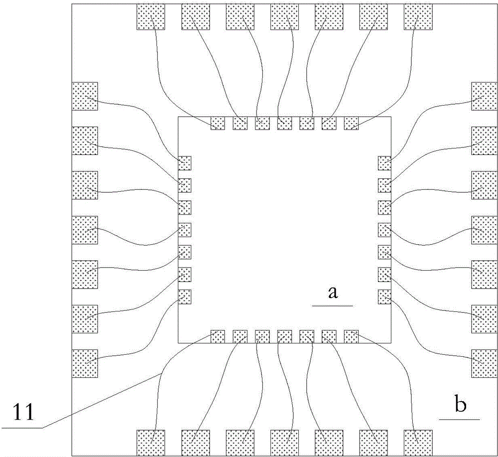
[0003] figure 1 It is a structural schematic diagram of a traditional MEMS chip integrated package; such as figure 1 As shown, in the traditional MEMS chip integration process, in order to reduce the overall packaging area, the chip a is first stacked on the chip b, and after the interconnection between the chip a and the chip b is realized through the wire 11, Then carry out the final packaging process; because the increased lead 111 will bring defects such as heat generation and increased power consumption, and when performing the bonding process, the lead 11 will also be adversely affected by various factors such as the process and the environment, and may even cause The failure of the device, thereby reducing the performance and yield of the prepared device product

Method used


Image

  • Micro-electromechanical systems (MEMS) device assembling technology
  • Micro-electromechanical systems (MEMS) device assembling technology
  • Micro-electromechanical systems (MEMS) device assembling technology

Examples


Embodiment Construction

[0036] In the following description, numerous specific details are given in order to provide a more thorough understanding of the present invention. It will be apparent, however, to one skilled in the art that the present invention may be practiced without one or more of these details. In other examples, some technical features known in the art are not described in order to avoid confusion with the present invention.

[0037] It should be understood that the invention can be embodied in different forms and should not be construed as limited to the embodiments set forth herein. Rather, these embodiments are provided so that this disclosure will be thorough and complete, and will fully convey the scope of the invention to those skilled in the art. In the drawings, the size and relative sizes of layers and regions may be exaggerated for clarity. Like reference numerals refer to like elements throughout.

[0038] It will be understood that when an element or layer is referred t...


PUM

PropertyMeasurementUnit
Diameteraaaaaaaaaa
Thicknessaaaaaaaaaa

Abstract

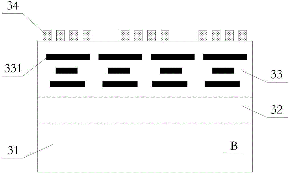
The invention relates to a micro-electromechanical systems (MEMS) device assembling technology and relates to the field of semiconductor device manufacture. The MEMS device assembling technology realizes connection of a MEMS chip and other semiconductor chips by direct bonding of the MEMS chip and the other semiconductor chips, utilizes a through-silicon-vias technology to prepare interconnection lines thereby realizing connection of a bonding chip and an external device and reducing connection lines connecting the chips, reduces device failure probability, saves a device packaging volume, reduces device power consumption, improves bonding chip heat conditions, effectively improves device performances and greatly improves a product yield rate.

Description

technical field [0001] The invention relates to the field of semiconductor device manufacturing, in particular to a MEMS device integration process. Background technique [0002] At present, as the application fields of MEMS (Micro-electromechanical Systems, micro-electromechanical systems) chips become more and more extensive, it is necessary to integrate and package MEMS chips with other semiconductor chips; and in order to save the packaging area of ​​the overall device structure, usually The stacking method sets the MEMS chip on top of other chips. [0003] figure 1 It is a structural schematic diagram of a traditional MEMS chip integrated package; such as figure 1 As shown, in the traditional MEMS chip integration process, in order to reduce the overall packaging area, the chip a is first stacked on the chip b, and after the interconnection between the chip a and the chip b is realized through the wire 11, Then carry out the final packaging process; because the incre...

Claims


Application Information

Patent Timeline
IPC IPC(8): B81C3/00B81C1/00
Inventor 黄海何晓峰黄建冬
Owner WUHAN XINXIN SEMICON MFG CO LTD
Learn More