Elliptical ring-cavity microcavity laser with high resistance region

A laser and ring cavity technology, which is applied in the field of elliptical ring cavity microcavity lasers, can solve the problems that the elliptical ring cavity cannot effectively select the radial mode, reduce the device yield, and the edge of the cavity is damaged, so as to improve the electro-optical conversion efficiency, Improvement of electro-optical conversion efficiency and improvement of yield

Active Publication Date: 2018-03-20
CHANGCHUN UNIV OF SCI & TECH
View PDF4 Cites 0 Cited by
  • Summary
  • Abstract
  • Description
  • Claims
  • Application Information

AI Technical Summary

Problems solved by technology

However, due to the limitation of the process characteristics of photolithographic mask wet etching or reactive ion etching method, the width of the elliptical annular structure is difficult to make very narrow, usually more than 30 microns, such as 50 microns, so The width of the elliptical annular cavity does not effectively select the radial mode
Moreover, compared to the elliptical annular structure with a long axis of 192 microns and a short axis of 160 microns, the removed ineffective current injection area is not too large, because the resonance of light in the whispering gallery mode still occurs in the peripheral area of ​​the elliptical annular cavity, Therefore, there is still a lot of ineffective current injection, and the effect in improving the electro-optical conversion efficiency is not ideal.
In addition, in the process of wet etching or reactive ion etching of photolithographic masks, due to the poor controllability of the process, the inner wall of the elliptical ring structure is rough, which introduces a large optical loss. In order to maintain effective light output, it is necessary to add High current injection, which may lead to device damage, resulting in low device yield
In addition, although the width of the upper electrode of the elliptical ring is relatively large, such as 50 microns, since the diameter of a single gold wire lead is more than 25 microns, such as 50 microns, so the lead wire of such thickness is welded on such a wide upper electrode. The electrode is still very difficult, which is easy to cause damage to the edge of the cavity and reduce the yield of the device; because it is impossible to weld multiple gold wire leads, it is difficult to increase the injection current, and it is difficult to achieve high optical power output

Method used


Image

  • Elliptical ring-cavity microcavity laser with high resistance region
  • Elliptical ring-cavity microcavity laser with high resistance region
  • Elliptical ring-cavity microcavity laser with high resistance region

Examples


Embodiment Construction

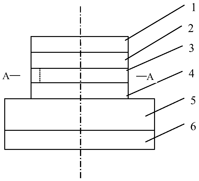
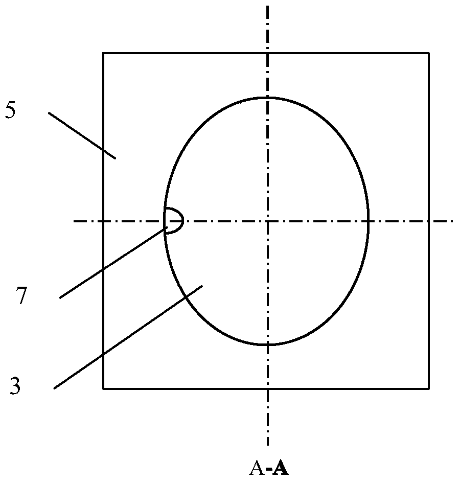
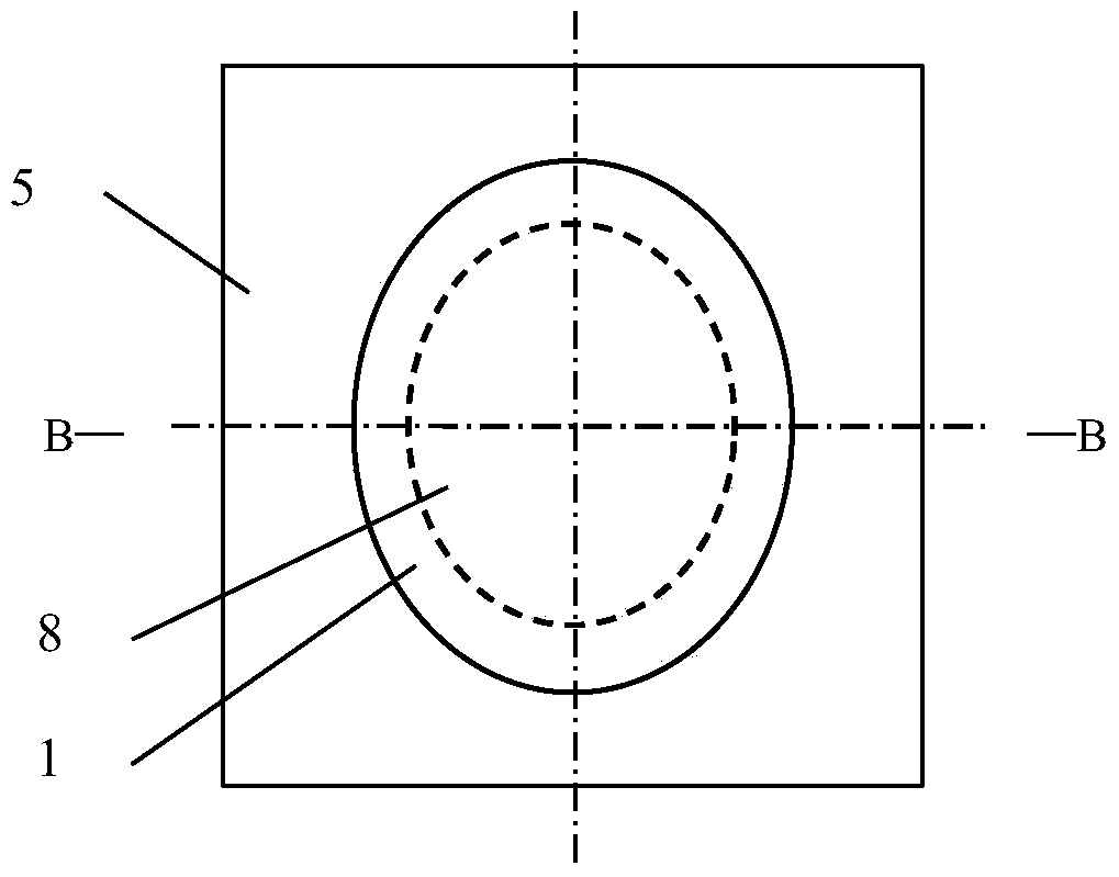
[0008] The components of the elliptical annular cavity microcavity laser with high resistance region of the present invention are upper electrode 1, upper waveguide layer 2, active gain layer 3, lower waveguide layer 4, substrate 5, and lower electrode 6 from top to bottom. , the lower electrode 6 is welded to the copper heat sink, the upper electrode 1, the upper waveguide layer 2, the active gain layer 3, and the lower waveguide layer 4 are elliptical discs, and there is a Semi-elliptical incision 7. The upper electrode 1 is a Ti-Au electrode. The upper waveguide layer 2 is InGaAsP. The active gain layer 3 is an InGaAs / InAlAs quantum cascade structure with an emission wavelength of 10 microns. The lower waveguide layer 4 is InGaAsP. The substrate 5 is InP. The lower electrode 6 is an Au-Ge-Ni electrode. The semi-major axis dimension of the outer boundary of the elliptical disk type is R y1 , R y1 = 96 microns, the semi-minor axis dimension is R x1 , R x1 = 80 micron...


PUM


Abstract

The invention belongs to the technical field of semiconductor lasers, discloses an elliptic ring microcavity laser with a high-resistance area, and aims to solve the problems that existing elliptic plate microcavity lasers are high in laser emission threshold, low in electro-optical conversion efficiency, high in temperature rise and low in light output power and existing elliptic ring microcavity semiconductor lasers are low in yield and difficult in realization of high light output power. The elliptic ring microcavity laser with the high-resistance area comprises an upper electrode, an upper waveguide layer, an active gain layer, a lower waveguide layer, a substrate and a lower electrode sequentially from top to bottom. The lower electrode is welded onto a copper heat sink, the upper electrode, the upper waveguide layer, the active gain layer and the lower waveguide layer are shaped in elliptic plates, and one end of an ellipse minor axis at the outer boundary of the active gain layer is provided with a semi-elliptic cut. The elliptic ring microcavity laser is characterized in that a central area of the upper waveguide layer is the high-resistance area, and the high-resistance area is formed by means of photomask and protonation before the upper electrode is made on the upper waveguide layer.

Description

technical field [0001] The invention relates to an elliptical annular cavity microcavity laser with a high resistance region, belonging to the technical field of semiconductor lasers. Background technique [0002] Among the existing microcavity lasers, there is a slitted elliptical disc cavity microcavity laser, which can produce light output in almost a single direction, as published in December 2010 in "Proceedings of the National Academy of Sciences of the United States of America ( PNAS) "page 22407 of the 107th issue has just recorded a kind of said elliptical disc cavity microcavity laser, as figure 1 , figure 2 As shown, its components from top to bottom are upper electrode 1, upper waveguide layer 2, active gain layer 3, lower waveguide layer 4, substrate 5, and lower electrode 6. The lower electrode 6 is welded to the copper heat sink by solder Above; there is a semi-elliptical cutout 7 at one end of the minor axis of the elliptical outer boundary of the elliptic...

Claims


Application Information

Patent Timeline
Patent Type & Authority Patents(China)
IPC IPC(8): H01S5/20H01S5/06
Inventor 晏长岭史建伟冯源郝永芹李鹏
Owner CHANGCHUN UNIV OF SCI & TECH
Why Eureka
Try Eureka