Method for encapsulating high-power IGBT device through performing non-pressure low-temperature sintering on nano silver soldering paste

A low-temperature sintering and nano-silver technology, which is applied in the manufacture of electrical solid devices, semiconductor devices, semiconductor/solid devices, etc., can solve problems such as low porosity, improve performance, simplify packaging process, improve work efficiency and service life Effect

Inactive Publication Date: 2015-03-04
TIANJIN UNIV
View PDF3 Cites 17 Cited by
  • Summary
  • Abstract
  • Description
  • Claims
  • Application Information

AI Technical Summary

Problems solved by technology

However, the existing packaging methods cannot realize that the connection layer of the chip still has a low porosity (less than 2%) during the pressureless sintering process of the nano-silver solder paste, which has become a problem that needs to be solved urgently.

Method used


Image

  • Method for encapsulating high-power IGBT device through performing non-pressure low-temperature sintering on nano silver soldering paste
  • Method for encapsulating high-power IGBT device through performing non-pressure low-temperature sintering on nano silver soldering paste
  • Method for encapsulating high-power IGBT device through performing non-pressure low-temperature sintering on nano silver soldering paste

Examples


example 1

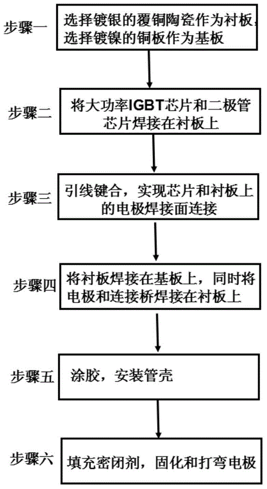
[0029] Example 1: First, ultrasonic and plasma are used to clean impurities on the surface of the liner and substrate. A cross-shaped solder paste is then printed on the solder side of the backing board. When the cross-shaped coverage area accounts for 30% of the total area of ​​the connection layer, paste the chip and make the nano-silver solder paste fully wet the chip until the solder paste spreads evenly around the chip. At this time, the thickness of the connection layer is 30% of the thickness of the screen printing solder paste layer. Then carry out sintering: from normal temperature to 250°C-270°C, and then keep warm for 10min-30min, the heating rate is 3-5°C / min. After sintering, the porosity is lower than 1%.

example 2

[0030] Example 2: First, ultrasonic and plasma are used to clean impurities on the surface of the liner and substrate. A cross-shaped solder paste is then printed on the solder side of the backing board. When the cross-shaped coverage area accounts for 50% of the total area of ​​the connection layer, paste the chip and make the nano-silver solder paste fully wet the chip until the solder paste spreads evenly around the chip. At this time, the thickness of the connection layer is 50% of the thickness of the screen printing solder paste layer. Then sintering: from normal temperature to 250°C, and then keep the temperature for 30 minutes, the heating rate is 5°C / min. After sintering, the porosity is between 1% and 1.5%.

example 3

[0031] Example 3: First, ultrasonic and plasma are used to clean impurities on the surface of the liner and substrate. A cross-shaped solder paste is then printed on the solder side of the backing board. When the cross-shaped coverage area accounts for 70% of the total area of ​​the connection layer, paste the chip and make the nano-silver solder paste fully wet the chip until the solder paste spreads evenly around the chip. At this time, the thickness of the connecting layer is 70% of the thickness of the screen printing solder paste layer. Then sintering: from normal temperature to 250°C, and then keep the temperature for 30 minutes, the heating rate is 5°C / min. After sintering, the porosity is between 1.5% and 2%.

[0032] The packaging scheme of the present invention is easy to operate, has good thermal cycle capability and thermal fatigue resistance, and at the same time has excellent electrical connection performance, and has extremely high popularization value.


PUM

PropertyMeasurementUnit
melting pointaaaaaaaaaa
sintering temperatureaaaaaaaaaa
softening pointaaaaaaaaaa

Abstract

The invention relates to a method for encapsulating a high-power IGBT device through performing non-pressure low-temperature sintering on nano silver soldering paste. The method includes the following steps that: the nano silver soldering paste is printed on a welding surface of a lining plate, the shape of the printed nano silver soldering paste is cross-shaped; a chip is arranged on the nano silver soldering paste which has been subjected to steel screen printing molding; and a heating stage is set to temperature from 250 DEG C to 270 DEG C, and sintering molding is performed. With the method adopted, void ratio can be lower than 2%. The use performance of the high-power IGBT module encapsulated through adopting the method can be improved, and encapsulation process can be simplified, and at the same time, it can be ensured that the adhesion strength of the chip which is higher than 30MP can satisfy use requirements in working, and it can be also ensured that a soldering paste layer has lower void ratio; and the work efficiency of the high-power IGBT module encapsulated through adopting the method can be improved, and the service life of the high-power IGBT module can be prolonged.

Description

technical field [0001] The invention relates to the technical field of packaging of power electronic devices, in particular to a method for packaging high-power IGBT devices by non-pressure low-temperature sintering nano-silver solder paste. Background technique [0002] The IGBT module is mainly used in the conversion system with a DC voltage of 600V and above, such as AC motors, frequency converters, switching power supplies, lighting circuits, traction drives and other fields. With its high input impedance, fast switching speed, low on-state voltage, high blocking voltage, and large current, IGBT has become the mainstream device in the development of power semiconductor devices today. IGBT modules have been widely used in UPS, induction heating power supply, inverter welding machine power supply and motor frequency conversion speed regulation and other power supply fields, and the market prospect is very broad. [0003] As the core device of the power electronic system, ...

Claims


Application Information

Patent Timeline
Patent Type & Authority Applications(China)
IPC IPC(8): H01L21/60
CPCH01L24/27H01L24/29H01L24/83H01L2224/2711H01L2224/29139H01L2224/29007H01L2224/29012H01L2224/29034H01L2224/838H01L2224/8384H01L2224/83191H01L2924/01047H01L2924/20107H01L2924/13055H01L2224/0603H01L2224/4846H01L2224/49111H01L2924/00
Inventor 梅云辉付善灿陆国权
Owner TIANJIN UNIV
Why Eureka
Try Eureka