Thin film composite membrane structures

A composite membrane, thin film technology, applied in membrane, membrane technology, semi-permeable membrane separation and other directions, can solve problems such as high cost and low efficiency

Active Publication Date: 2015-03-04
3M INNOVATIVE PROPERTIES CO +1
View PDF11 Cites 3 Cited by
  • Summary
  • Abstract
  • Description
  • Claims
  • Application Information

AI Technical Summary

Problems solved by technology

[0008] Technologies currently in use can be inefficient and expensive

Method used


Image

  • Thin film composite membrane structures
  • Thin film composite membrane structures
  • Thin film composite membrane structures

Examples


example 1

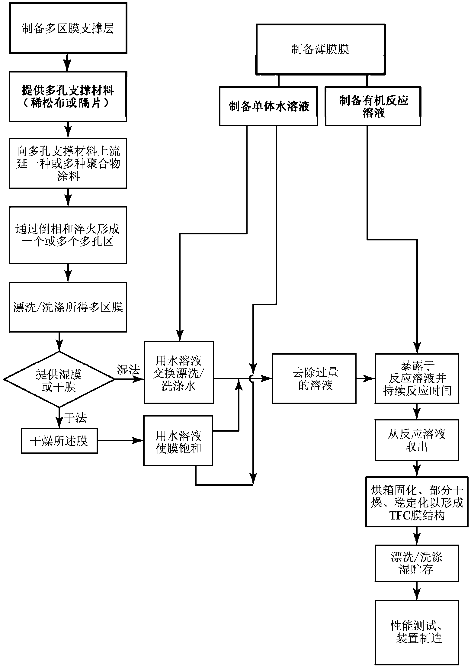
[0077] The procedure demonstrating the fabrication of these TFC membrane structures by PIP-based interfacial polymerization of polyamides is as follows:

[0078]The monomers used for this in situ interfacial polymerization of poly(piperazinamide) are PIP and TMC. PIP was dissolved in Milli-Q water at different concentrations ranging from 0.25% to 3% (w / v). To the aqueous PIP solution was added triethylamine (TEA) in a weight ratio of 1 / 1 relative to the amount of PIP. A 0.15% (w / v) trimesoyl chloride (TMC) / hexane solution was prepared. Both solutions were stirred at room temperature for a minimum of 3 hours before use.

[0079] A BLA010 nylon 6,6 microfiltration (MF) membrane / support layer was placed on a flat glass plate with the large pore side facing the glass plate and all edges sealed with tape. First soak the MF membrane into the PIP / TEA aqueous solution for 2 min. The MF membrane was placed into the solution so that the backside of the plate was not soaked in the so...

example 2

[0083] contrast

[0084] Commercially available asymmetric cellulose triacetate (HTI-CTA) forward osmosis (FO) membranes (Hydration Technology Innovations Inc., Albany, OR), TFC nanofiltration membrane NF270 and TFC seawater RO membrane SW30-XLE (Dow Water & Process Solutions Company, Midland, MI) for comparison. These membranes have three layers: a polyamide selective film layer, a microporous polysulfone (PSu) interlayer, and a high strength polyester support web.

example 3

[0086] experimental method

[0087] The surface morphology of the BLA010MF support and the TFC polyamide membrane was qualitatively evaluated by scanning electron microscopy (SEM) using a cold cathode field emission scanning electron microscope JSM-6335F (FEI, USA). Before imaging, the samples were kept in a desiccator overnight and sputter coated with a thin layer of platinum for better contrast and to avoid charge buildup.

[0088] The surface morphology of the BLA010MF support and the TFC polyamide membrane was qualitatively evaluated by scanning electron microscopy (SEM) using a cold cathode field emission scanning electron microscope JSM-6335F (FEI, USA). Before imaging, the samples were kept in a desiccator overnight and sputter coated with a thin layer of platinum for better contrast and to avoid charge buildup.

[0089] The cross-sectional structure of the BLA010 support and the selective layer of the TFC membrane were also imaged with SEM. These samples were prepa...


PUM

PropertyMeasurementUnit
thicknessaaaaaaaaaa
sizeaaaaaaaaaa
particle sizeaaaaaaaaaa

Abstract

Provided are thin film composite membrane structures comprising: a selective membrane layer for ion rejection attached to a support layer, the support layer comprising a multi-zone microfiltration membrane comprising: a porous support material; and at least two microfiltration zones, where a first zone comprises a first membrane and a second zone that is attached to the first zone and that coats at least a portion of the porous support material. Thin film composite membrane structures may be provided in reverse osmosis systems or nanofiltration systems. Also, thin film composite membrane structures may be provided in direct osmotic concentration systems, forward osmosis systems, or pressure retarded osmosis systems.

Description

[0001] Cross references to related patent applications [0002] This patent application claims priority to US Provisional Patent Application 61 / 621,750, filed April 9, 2012, the disclosure of which is incorporated herein by reference in its entirety. [0003] Federally funded research and development [0004] This invention was made with US Government support under CBET #1067564 awarded by the National Science Foundation. The US Government has certain rights in this invention. technical field [0005] The present invention relates to the field of separation by means of ion-retaining membranes which employ a composite structure having a thin-film ion-retaining layer and a support. The support may in particular be a membrane having a plurality of separation regions. Background technique [0006] Global freshwater supplies are under threat. Reverse osmosis, nanofiltration and engineered osmosis (ie, direct osmosis concentration and forward osmosis) technologies will help...

Claims


Application Information

Patent Timeline
Patent Type & Authority Applications(China)
IPC IPC(8): B01D69/12B01D69/10B01D69/02B01D71/56B01D71/82
CPCC02F1/441B01D69/12B01D71/56B01D71/82C02F1/442B01D69/125B01D2325/04B01D67/0006B01D2323/40B01D2323/42B01D2325/02
Inventor 杰弗瑞·R·麦卡琴托马斯·J·哈姆林马克·T·迈林L·黄
Owner 3M INNOVATIVE PROPERTIES CO
Why Eureka
Try Eureka