Controllable heat-removing reactor

A reactor and heat transfer technology, applied in chemical instruments and methods, inorganic chemistry, non-metallic elements, etc., can solve the problems of difficulty in large-scale, low yield of long carbon chain alkanes, large resistance, etc. Effect

Active Publication Date: 2015-03-11
NANJING DUNXIAN CHEM TECH
View PDF10 Cites 12 Cited by
  • Summary
  • Abstract
  • Description
  • Claims
  • Application Information

AI Technical Summary

Problems solved by technology

[0006] The Fischer-Tropsch synthesis reaction of coal-to-oil and coal-to-paraffin has not yet operated a large-scale device, and some small-scale Fischer-Tropsch synthesis reactors in operation are also tubular reactors, and Fe (or Co) series catalysts are packed in ф76X4 In the tube, there are still defects such as uneven gas distribution, overheating, carbon deposition, low yield of long-carbon paraffins, high resistance, equipment leakage, and difficulty in large-scale expansion.

Method used


Image

  • Controllable heat-removing reactor
  • Controllable heat-removing reactor
  • Controllable heat-removing reactor

Examples


Embodiment 1

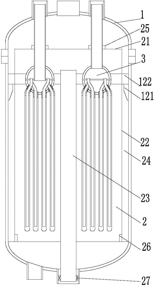
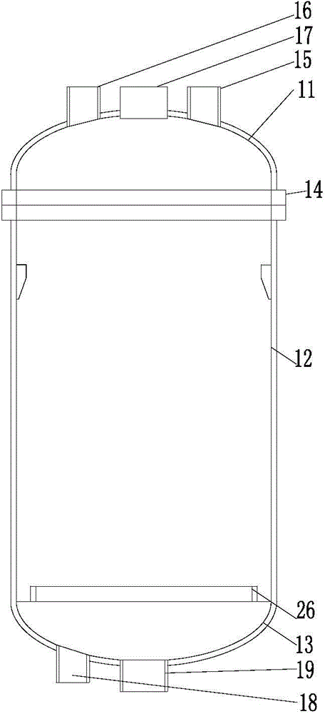
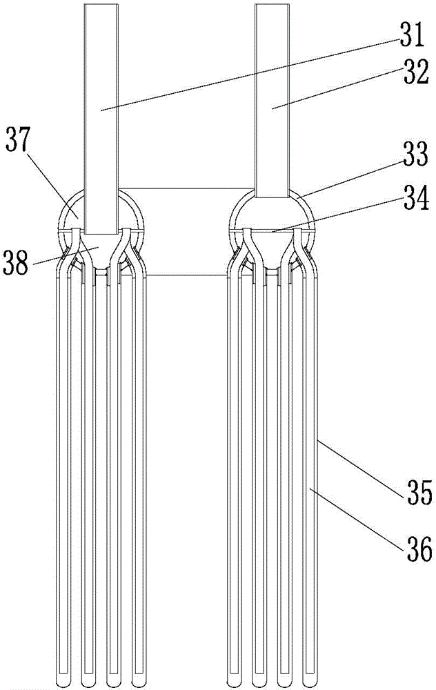
[0033] Such as picture 1, picture 2 and picture 3, this embodiment includes a pressure-bearing shell 1, a sealed catalyst frame 2 arranged in the pressure-bearing shell 1, and a heat transfer tube bundle 3 for self-circulation of the water circuit. The sealed catalyst frame 2 is coated on the heat transfer Outside the tube bundle 3; the heat transfer tube bundle 3 includes a water outlet main pipe 31, a water inlet main pipe 32, a ring pipe 33, a partition 34, a cecum-type heat exchange tube 35 and a water guide pipe 36; the partition 34 is arranged in the middle of the ring pipe 33 , the upper and lower parts of the ring pipe 33 are divided into a water distribution tank 37 and a water collection tank 38, the water inlet main pipe 32 communicates with the water distribution tank 37 on the upper part of the ring pipe 33, the water outlet main pipe 31 communicates with the water collection tank 38 at the lower part of the ring pipe 33, and 36 sets of water guide pipes Set in ...

Embodiment 2

[0046] This embodiment is applied to a 400,000-ton / year synthetic ammonia plant with a low water / gas ratio, and other implementations are the same as in Embodiment 1.

[0047] 1. Design conditions and requirements:

[0048] Change gas volume: 160273Nm 3 / h

[0049] Working pressure: 2.1MPa

[0050] Working temperature: 35~40℃

[0051] The gas composition is:

[0052] serial number name CO 2 % CO% H 2 % O 2 % N 2 % CH 4 % 1 semi water gas 7.87 29.3 46.03 0.3 15.19 1.02 2 change gas 24.00 4~8 55.40 0 12.60 0.85

[0053] 2. Compared with the adiabatic shift reactor of the traditional full low-variation process, the present invention can bring the following energy saving:

[0054] .


PUM


Abstract

The invention discloses a controllable heat-removing reactor. A heat-removing pipe bundle comprises a water outlet main pipe, a water inlet main pipe, a ring pipe, a partition board, a cecum-type heat exchange tube and a water guide pipe; the partition board is arranged in the middle part of the ring pipe, and is used for partitioning the upper part and the lower part of the ring pipe into a water distribution box and a water collection box; the water inlet main pipe is communicated with the water distribution box at the upper part of the ring pipe; the water outlet main pipe is communicated with the water collection box at the lower part of the ring pipe; the water guide pipe is arranged inside the cecum-type heat exchange tube in a sleeving mode; one end of the cecum-type heat exchanger is open, and the other end of the cecum-type heat exchanger is closed; the open end of the cecum-type heat exchanger is communicated with the water collection box at the lower part of the ring pipe; openings are formed in the two ends of the water guide pipe; the top of the water guide pipe is communicated with the water distribution box at the upper part of the ring pipe; the bottom of the water guide pipe is positioned above the closed end of the cecum-type heat exchanger. A catalyst frame and the heat-removing pipe bundle of the controllable heat-removing reactor are separated from a pressure-bearing shell, so that maintenance, catalyst self-discharging and catalyst filling are facilitated; a heat-removing water pipe is buried inside a catalyst bed, so that the heat of reaction inside the catalyst bed can be removed in time.

Description

Technical field [0001] The present invention involves a fixed bed catalytic reaction device, which especially involves a controllable heating reactor. Background technique [0002] After the CO transformation reaction, as a widely used reactor in the chemical industry, people have improved many times to the transformation reactor. From the original full axis to the full radial, it has achieved goodThe effect, but the catalyst bed layer is still the heating reaction. The catalyst bed layer is divided into several beds. Each bed layer is indirectly replaced with heat exchange or water cooling.This indirect heat exchange recovery and transformation system has low thermal energy quality, recycling heat showing heat and low -inside heat efficiency, easy catalysts such as over temperature, and mixed with methane at the same time. [0003] The radiant synthetic synthetic reactor of the coal -to -ethylene glycol is currently used in the tube of the ф25X2 to fill the catalyst. The water i...

Claims


Application Information

Patent Timeline
Patent Type & Authority Applications(China)
IPC IPC(8): B01J8/02C01B3/16
CPCB01J8/0015B01J8/02B01J8/0285C01B3/16C01B2203/0227
Inventor 王庆新王揽月
Owner NANJING DUNXIAN CHEM TECH
Why Eureka
Try Eureka